Do you have a question about the Samsung S1000 and is the answer not in the manual?
Essential safety measures to prevent hazards like electric shock and protect the unit.
Guidelines for safe and effective servicing procedures to avoid damage or injury.
Measures to prevent damage to sensitive electronic components from static discharge.
Specific warnings and precautions related to the safe operation of laser products.
Step-by-step instructions for disassembling the frame-jersey component.
Guide for safely removing and disassembling the front panel assembly.
Procedure for disassembling the main frame assembly.
Instructions for disassembling the key-assembly, including door operation.
Detailed steps for aligning the tuner for optimal performance.
Procedures for adjusting tape speed, playback head, and recording levels.
Steps for aligning the CD player's tracking, focus, and balance.
Detailed explanations of the CD player's internal circuitry and components.
Description of the RF amplifier circuit and its function.
Explanation of the focus error amplifier circuit.
Details on the focus servo system and its phase compensation.
Description of the tracking sled servo system.
Diagnostic steps for amplifier power and audio output malfunctions.
Steps to diagnose and resolve FLT (Front Logic) malfunctions.
Procedures to identify and fix issues causing no audio output.
Guide for diagnosing power, FLT, and no output issues on the cassette deck.
Steps for resolving CD player malfunctions like disc revolution and audio output.
Visual exploded diagram of the cassette deck mechanism.
Overall exploded view of the main unit components.
Detailed list of parts for the cassette deck and main unit.
Overview of the main system's functional blocks and interconnections.
Block diagram illustrating the CD player's system architecture.
Internal circuit diagrams for key ICs and transistors used in the system.
Block diagram detailing the functionality of the micro-com (UIC1).
Diagram showing the layout and component placement on the main PCB.
Diagram illustrating the component layout on the front PCB.
Diagram showing the component layout for the CD PCB.
Detailed schematic of the main system circuitry.
Detailed schematic for the front section of the unit.
Detailed schematic illustrating the CD player circuitry.
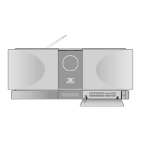
| Brand | Samsung |
|---|---|
| Model | S1000 |
| Category | Speaker System |
| Language | English |