Do you have a question about the Samsung SH07AWHX and is the answer not in the manual?
Detailed specifications table for indoor and outdoor units.
Graph illustrating low pressure vs. outdoor drybulb temperature.
Explains the functions of various buttons on the remote control.
Describes operation properties for AUTO, COOL, HEAT, DRY, TURBO, SLEEP modes.
Pre-installation checks and considerations for the unit.
Step-by-step guide for the installation process.
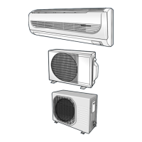
Visual guide for connecting and setting up unit components.
Steps for purging air from the system during installation.
Procedure for refilling the R410A refrigerant.
Steps for pumping down refrigerant when relocating or replacing parts.
Detailed steps for disassembling the indoor unit components.
Detailed steps for disassembling the outdoor unit components.
Instructions for configuring model-specific options via remote control.
Initial checks for common operational problems and voltage requirements.
Diagnosing issues based on initial status and lamp indicators.
Detailed troubleshooting flowcharts for various component failures.
Procedure to diagnose and fix room temperature sensor issues.
Procedure to diagnose and fix room pipe sensor issues.
Troubleshooting steps for a non-operating indoor fan motor.
Troubleshooting steps for issues with power supply or unit startup.
Diagnosing why the outdoor unit is not operating.
Troubleshooting steps for lack of warm air in heat mode.
Troubleshooting steps for the louvre motor not operating.
Troubleshooting steps for issues with remote control reception.
Procedures for inspecting and testing Printed Circuit Boards (PCBs).
Important precautions before inspecting PCBs.
General steps for inspecting PCB components.
Specific tests and checks for PCB functionality.
Table converting room temperature sensor resistance values.
Methods for inspecting major components like sensors and motors.
Exploded view diagram and parts list for the indoor unit.
Exploded view diagram and parts list for the outdoor unit.
Exploded view and parts list for the control assembly.
Electrical wiring diagram for the indoor unit.
Electrical wiring diagram for the outdoor unit.
| Brand | Samsung |
|---|---|
| Model | SH07AWHX |
| Category | Air Conditioner |
| Language | English |