Do you have a question about the Samsung SH09APG and is the answer not in the manual?
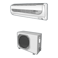
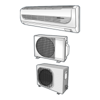
Detailed specifications for different models, including cooling/heating capacity, air volume, noise, and power.
Visual representation of low pressure versus outdoor drybulb temperature for different models.
Explains the function of each button on the air conditioner's remote control.
Details the specific operations and modes controlled by remote keys like AUTO, COOL, HEAT, DRY, FAN, TURBO, SLEEP.
Step-by-step guide for replacing and setting up the PCB model option.
Procedures for safely disassembling the indoor unit components for maintenance or repair.
Procedures for safely disassembling the outdoor unit components for maintenance or repair.
Illustrates the flow of refrigerant through the indoor and outdoor units during cooling and heating cycles.
Instructions on how to enter and configure model-specific options using the remote control.
Basic checks to perform before diagnosing operational issues with the air conditioner.
Detailed symptom-based troubleshooting for various operational failures and error codes.
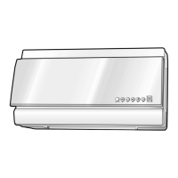
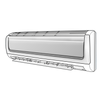
Visual breakdown of indoor unit components with corresponding part numbers and quantities.
Visual breakdown of outdoor unit components with corresponding part numbers and quantities.
Diagram and parts list for the indoor unit's control assembly.
High-level overview of the system's functional blocks and their interconnections.
Detailed layout and component identification for the main Printed Circuit Board.
Diagram illustrating the components and connections of the display Printed Circuit Board.
Diagram illustrating the components and connections of the module Printed Circuit Board.
Electrical schematic showing all connections within the indoor unit.
Electrical schematic showing all connections within the outdoor unit.
Comprehensive circuit diagram detailing the electronic components and their interconnections.
| Type | Split System |
|---|---|
| Cooling Capacity | 9000 BTU/h |
| Power Supply | 220-240V, 50Hz |
| Refrigerant | R410A |
| Energy Efficiency Ratio (EER) | 3.2 |