T
Thomas CunninghamAug 6, 2025
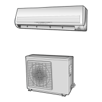
What to do if my Samsung SH12ZS4AX remote control is not working?
- SStanley KelleyAug 6, 2025
If your Samsung Air Conditioner remote control isn't working, first try unplugging the air conditioner, waiting 5 seconds, and then plugging it back in. If that doesn't work, the remote control or the receiver on the indoor unit might be faulty. Try pressing the (ON/OFF) button on the indoor unit. If it still doesn't respond, the indoor unit may have a problem.