EasyManua.ls Logo

Samsung SP-R5100 - User Manual

Samsung SP-R5100
8 pages
Print Icon
To Next Page IconTo Next Page
Loading...
Cordless Telephone
SP-R5100
CONTENTS
1.
Safety Precautions
2.
Specification
3. Function Structures
4. Test Mode
5.
Component Pin Array
6. Alignment & Adjustment
7.
Trouble Shooting
8.
PCB Views
9.
Electrical Parts List
10.
Exploded Views and Parts List
11. Block Diagram
12. Schematic Description and Diagrams
Cordless Telephone
SERVICE
Manual
S E C R E T
Question and Answer IconNeed help?

Do you have a question about the Samsung SP-R5100 and is the answer not in the manual?

Summary

Schematic Description & Diagrams

Handset RF Circuit Overview

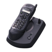
Introduces the handset RF system, T.D.D. method, frequency range, and DECT RF module.

Handset RF Module Pin Assignments

Details the pin assignments and functions of the handset's RF module.

Handset Logic Circuitry

Handset Logic, Keypad & EEPROM

Describes handset logic control, keypad matrix, and EEPROM functions.

RSSI, Power, Audio & Charging Circuits

Explains RSSI detection, power supply, audio signal processing, and charging methods.

Baseset RF Circuitry

Baseset RF & Antenna Overview

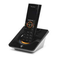
Introduces the baseset RF circuit, its similarity to handset RF, and antenna types.

Baseset RF Module Pin Assignments

Details the pin assignments and functions of the baseset RF module.

Baseset Logic Circuitry

Baseset Logic & Telephone Interface

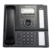
Covers baseset logic control and the telephone line interface functions.

Power, Ring Detection, Audio & Indication

Explains power supply, ring detection, audio processing, and status indication circuits.

Charger Circuit

Samsung SP-R5100 Specifications

General IconGeneral
BrandSamsung
ModelSP-R5100
CategoryCordless Telephone
LanguageEnglish

Related product manuals