Do you have a question about the Samsung SR-40RMB and is the answer not in the manual?
Defines warning and caution symbols and their meanings for user safety.
Provides essential safety instructions regarding electrical hazards, power cords, and proper appliance handling.
Lists specific cautions for storing items and handling product parts to prevent injury or damage.
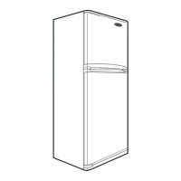
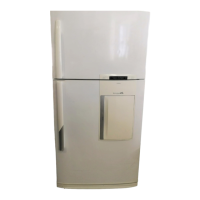
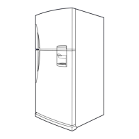
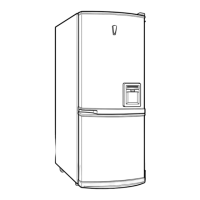
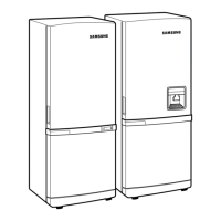
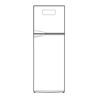
Provides detailed dimensions of the refrigerator models in a tabular format.
Step-by-step guide on how to remove various internal shelves and bins from the refrigerator.
Illustrates the path of coolant gas through various components like compressor, evaporator, and condenser.
Explains how cold air is distributed within the freezer and refrigerating compartments.
Details how to select freezer and refrigerator temperatures and the defrosting function.
Describes forced starting and defrosting functions for testing purposes and release mode.
Explains the self-diagnosis process, defect indication, and troubleshooting steps for sensors.
Details the power supply circuit, including voltage regulation and component connections.
Explains the oscillation circuit responsible for generating clocks for synchronization.
Describes the reset circuit's function to initialize program functions upon power supply or failure.
Explains the circuit for detecting the refrigerator door open/closed status.
Details the circuit diagram for temperature sensors and their resistance-voltage conversion.
Explains the rotary switch circuit used for temperature control settings.
Describes how compressor, defrost heater, and indicator lamp operations are controlled by the micro-controller.
Details the table of temperature changes related to diode options and warnings against voluntary changes.
Provides a flowchart for diagnosing and resolving issues related to refrigerator temperature being too high or low.
Outlines a flowchart for checking power input, fuse, soldering, and relay operations of the main PCB.
Provides safety standards, file numbers, ordering information, and coil data for VSB relays.
Details the features, contact arrangement, material, ratings, and coil specifications of the relay.
Illustrates the relay structure and provides general information like insulation and time values.
Provides electrical characteristics, absolute maximum ratings, and test conditions for voltage detectors.
Lists voltage regulators (KA78XX series) with their features, ordering information, and block diagram.
Details electrical characteristics, pin configuration, and schematic diagrams for the KA2657 driver IC.
Guides on checking symptoms, causes, and suggestions for cooling cycle malfunctions.
Methods and criteria for testing compressor, PTC relay, condenser, overload protector, and fan motor.
Methods and criteria for testing door switch, defrost heater, and their normal/abnormal states.
Step-by-step instructions for removing and handling the COVER-EVAP ASS'Y from the freezing compartment.
Instructions for removing the chiller compartment and replacing the light bulb in the refrigerating section.
Steps for removing the light cover and replacing the freezer light bulb, if equipped.
Provides instructions for removing the freezer and refrigerator doors, including hinge separation.
Instructions for reassembling the refrigerator and freezer doors after hinge adjustments or exchange.
| Model | SR-40RMB |
|---|---|
| Brand | Samsung |
| Type | Refrigerator |
| Height | 1785 mm |
| Freezer Features | Ice Maker |
| Cooling System | Twin Cooling Plus |