3-1-3 Removing the Main PCB
1. Complete all previous steps.
2. Disconnect the Degaussing Coil at GT601 and
GT602 on the Main PCB.
3. Disconnect all easily accessible ground wires
on the Main PCB and Bottom Chassis.
4. Disconnect the DY connector at the CN303
connector on the Main .
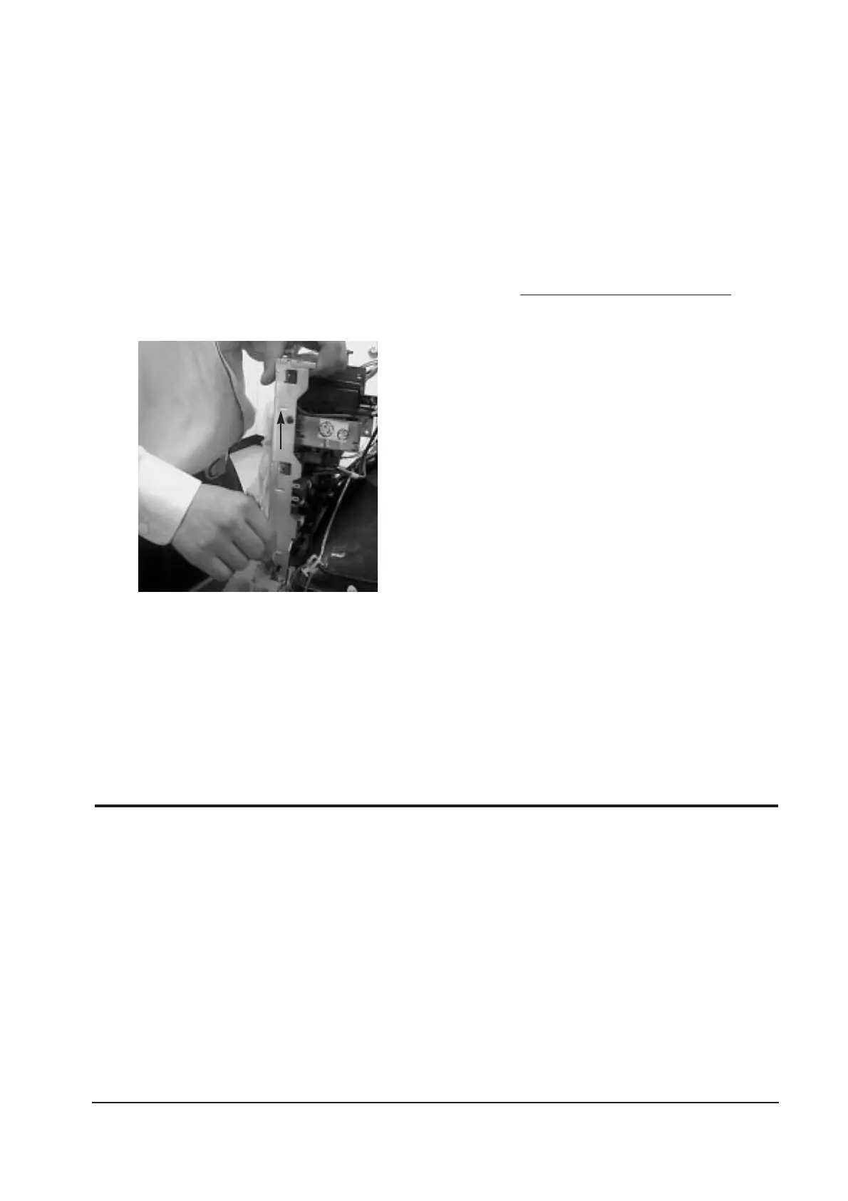
5. Using the jig, release the snaps (2) connecting
the Front Cover and Main PCB then lift up the
Bottom to separate the two Shield.
6. Remove the screws on the back and along
each side of the Bottom Chassis.
7. Carefully lift the Main PCB Ass’y and remove
the remaining ground wires.
8. Place the Main PCB Ass’y on a flat, level
surface that is protected from static electricity.
3-1-4 CRT Ass’y Disassembly
1. Complete all previous steps.
2. Straighten the Degaussing Coil Assembly
coated metal ties and lift the Coil Ass’y from
the CRT.
3. Remove the four corner screws and lift the
CRT up and away from the Front Cover
Assembly and place it on a padded surface.
Caution: Do not lift the CRT by the neck.
If you will be returning this CRT to
the monitor, be sure to place the CRT
face downward on a protective pad.
3 Disassembly and Reassembly
SyncMaster 753DF/755DF 3-3
Figure 10
3-2 Reassembly
Reassembly procedures are in the reverse order of Disassembly procedures.