12 S&C Instruction Sheet 665-506
Installation
Cable Terminations
Step 3
Ç
DANGER
Before energizing the gear, replace the shipping caps on all bushings and bushing wells
with elbows or insulated protective covers or plugs. Failure to replace the shipping
caps can result in a flashover and serious personal injury or death.
Switch terminals are equipped with 600-ampere-rated bushings, and fuse terminals are
equipped with 200ampere-rated bushing wells. Bushing and bushing-well interfaces conform
to ANSI/IEEE Standard 386 to accept all standard separable insulated connectors—
“elbows”—and inserts. Appropriate elbows
m
and inserts must be supplied and installed by
the user. Before installing elbows and inserts, remove the shipping covers from bushings
and bushing wells. Ground each insert by connecting a short ground wire from the insert
to the ground tab directly above the bushing well. See Figure 9 on page 11.
m Switch-termination compartments cannot accommodate 600-ampere elbows manufactured by Blackburn
when piggybacked.
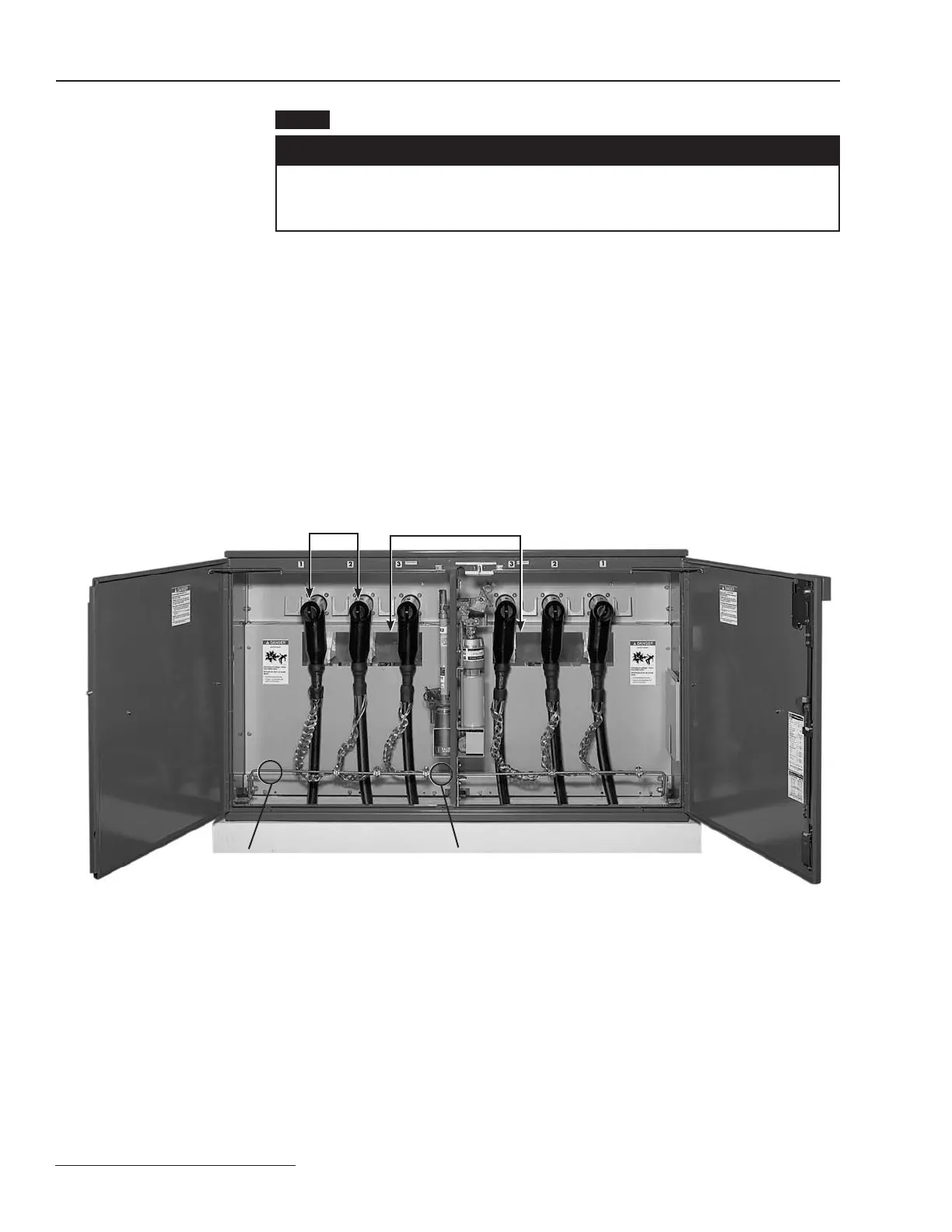
Figure 10. Bushings for Mini-Rupter® Switches are available with and without studs to accommodate all 600-ampere elbows.
Viewing windows allow visual verification of switch position
Ground rods extend full width of compartment
600-ampere bushings without studs are
furnished when Catalog Number Suffix “-M1”
is specified
 Loading...
