Interface Description SanDisk CompactFlash Card OEM Product Manual
The SanDisk CompactFlash Memory Card signals are described in Table 3-4.
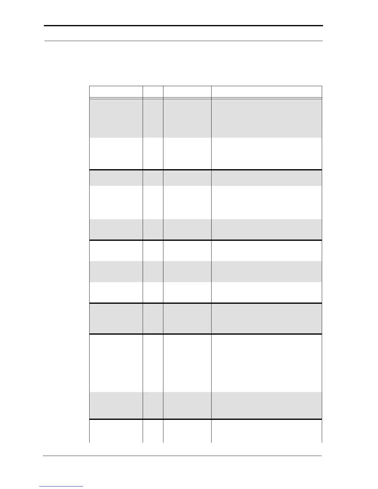
Table 3-4 Signal Description
Signal Name Dir. Pin Description
A10-A0
(PC Card Memory Mode)
(PC Card I/O Mode)
A2-A0
(True IDE Mode)
A10-A3
(True IDE Mode)
I
I
8, 10, 11, 12, 14,
15, 16, 17, 18, 19,
20
18, 19, 20
These address lines, along with the -REG
signal, are used to select the following: I/O port
address registers within the card, memory-
mapped port address registers within the card,
a byte in the card's information structure and its
configuration control and status registers.
In True IDE Mode only A[2:0] is used to select
one of eight registers in the Task File.
In True IDE Mode these remaining address
lines should be grounded by the host.
BVD1
(PC Card Memory Mode)
-STSCHG
(PC Card I/O Mode)
-PDIAG
(True IDE Mode)
I/O 46 This signal is asserted high as the BVD1 signal
since a battery is not used with this product.
The Status Changed signal is asserted low to
alert the host to changes in the RDY/-BSY and
Write Protect states, while the I/O interface is
configured. Its use is controlled by the Card
Config. and Status Register.
In the True IDE Mode, this input/output is the
Pass Diagnostic signal in the master/slave
handshake protocol.
BVD2
(PC Card Memory Mode)
-SPKR
(PC Card I/O Mode)
-DASP
(True IDE Mode)
I/O 45 This output line is always driven to a high state
in Memory Mode since a battery is not required
for this product.
This output line is always driven to a high state
in I/O Mode since this product does not support
the audio function.
In the True IDE Mode, this input/output is the
Disk Active/Slave Present signal in the master/
slave handshake protocol.
-CD1, -CD2
(PC Card Memory Mode)
(PC Card I/O Mode
)
(True IDE Mode)
O 26, 25 These Card Detect pins are connected to
ground on the card. They are used by the host
to determine if the card is fully inserted into its
socket.
-CE1, -CE2
(PC Card Memory Mode)
(PC Card I/O Mode)
-CS0, -CS1
(True IDE Mode)
I 7, 32 The Card Enable input signals are used both to
select the card and to indicate to the card
whether a byte or a word operation is being
performed. -CE2 always accesses the odd
byte of the word. -CE1 accesses the even byte
or the Odd byte of the word depending on A0
and -CE2. A multiplexing scheme based on
A0, -CE1, -CE2 allows 8 bit hosts to access all
data on D0-D7.
In True IDE Mode, -CS0 is the chip select for
the Task File registers while -CS1 is used to
select the Alternate Status Register and the
Device Control Register.
-CSEL
(PC Card Memory Mode)
(PC Card I/O Mode)
I 39 This signal is not used for PC Card Memory
Mode or PC Card I/O Mode.
02/07, Rev. 12.0 3-4 © 2007 SanDisk Corporation