20
ENGLISH
}
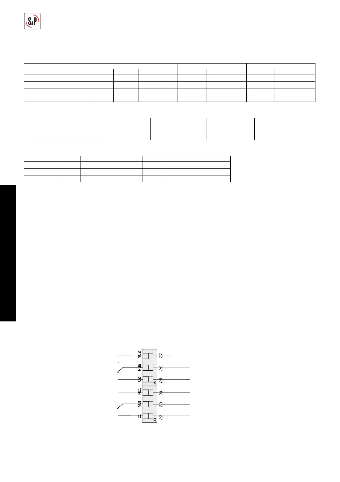
Alarm relay
output 2
}
Alarm relay
output 1
Adjustment values
Inputs:
Sensor Unit Scale Set point Proportional band
Min. Max. Increase Factory setting Increase Factory setting Increase Factory setting
Pressure Pa 0 2500 50 300 10 150 --- ---
%HR % 0 100 10 100 5 70 5 40
CO2 ppm 0 2000 100 2000 100 1000 100 1000
Temp. ºC 0 50 5 50 1 22 1 5
Outputs:
Unit Min. Max. Increase Factory settings
Minimum speed (OUT MIN) RPM 0% 50% 5% 10%
Maximum speed (OUT MAX) RPM 50% 100% 5% 100%
Alarms:
Min. Max. Increase Factory settings
S1 ALARM 0% 100% 5% 90% 0,9 x 100 = 90%HR
S2 ALARM 0% 100% 5% 90% 0,9 x 2000 = 1800 ppm
S3 ALARM 0% 100% 5% 90% 0,9 x 50 = 45%HR
LED ERROR - OUTPUT RELAYS
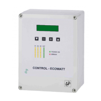
CONTROL ECOWATT models include an LED "ERROR" on the front panel and in the circuit of
the two relays RL1 and RL2. They have the following functions:
The function of relay 1 (J13) is Alarm or Error, together with the LED “ERROR”.
Activation:
1. When all the sensors read 0 for 2s. The J13 relay is locked and the LED “ERROR” is lit.
“S1 ERROR” appears on the display.
If this happens, check the sensor connections that show "error" on the display.
2. In the PROPORTIONAL setting, when the alarm sensor limits are exceeded (S1 ALARM,
S2 ALARM, S3 ALARM). The LED “ERROR” flashes twice. “S1 ALARM” appears on the
display.
The function of relay 2 (J5), in the MIN-MAX setting, is to activate the high speed of a two-
speed motor (2-windings single phase motor) when there is a change of input
 Loading...