3
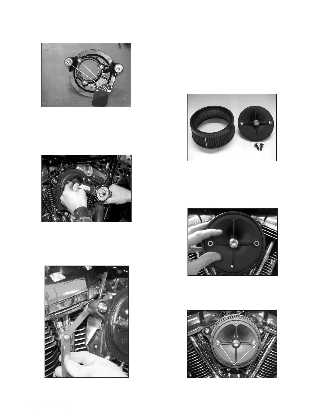
6. Apply a drop of 243 blue Loctite® to the threads of each screw and
breather bolt. Picture 7 illustrates all ve fasteners that require
243 blue Loctite.
Picture 7
Apply 243
Loctite®
7. Fit the backplate to the throttle body and the cylinder heads. Start
the threads of all the screws and tighten evenly until the backplate
is snug.
8. Now that the backplate is positioned, nish torque the ¼"-20
fasteners to 72 in.-lbs. as illustrated in Picture 8.
Picture 8
9. Check between the cylinder head and the backplate for air gaps.
NOTE: A feeler gauge works well for determining the amount of gap, if
any, between the head and the backplate as illustrated in Picture 9.
Picture 9
10. If a gap less than the thickness of a rubber coated washer is present,
torque the breather bolts down 10-12 ft.-lbs. If a gap of more than
the thickness of a rubber coated washer is present, determine
how much and select the appropriate number of rubber coated
washers needed to take up the gap.
11. If more than one rubber coated washer is needed between the
head and backplate, back out the breather bolts and install the
correct number of rubber coated washers.
12. Thread the breather bolts in and nish torque breather bolts to
10-12 ft.-lbs.
13. Locate the lter, plastic lter top plate and the two ¼"-20 anged
head fasteners as illustrated in Picture 10.
Filter Top Plate
Filter
Flanged Head Screws
Picture 10
14. Apply a drop of 243 blue Loctite® to the threads of each ¼"-20
anged head screw and set aside.
15. Hold the lter on the backplate and put the lter top plate on top
of the lter making sure that the word “Down” is facing down and
sitting at on the lter and locked into the groove as illustrated in
Picture 11.
Picture 11
DOWN
16. Pass the ¼"-20 anged head screws through the plastic top lter
plate, thread in and tighten down evenly until snug and then nish
torque to 72 in.-lbs. as illustrated in Picture 12.
Picture 12
Torque to 72 in.-lbs.
 Loading...