EasyManua.ls Logo

S&T Kontron VX3060 - User Manual

S&T Kontron VX3060
114 pages
Print Icon
To Next Page IconTo Next Page
Loading...

USER GUIDE
www.kontron.com // 2
VX3060 & VX3060-S2
3U VPX Computing Node
D247914-V1.2 Apr 2022

Table of Contents

Question and Answer IconNeed help?

Do you have a question about the S&T Kontron VX3060 and is the answer not in the manual?

Summary

Customer Support

Symbols

For Your Safety

High Voltage Safety Instructions

Instructions for safe handling of high voltage components.

Special Handling and Unpacking Instruction

Precautions for handling and unpacking sensitive devices.

General Instructions on Usage

Introduction

Manual Overview

Explains the manual's objective, audience, scope, and structure.

VPX Overview

Overview of VPX (VITA 46) specifications for bus boards.

Board Overview

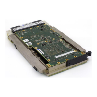
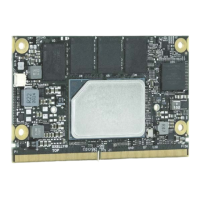
Details the main features and overview of the VX3060 board.

Terminology, Definitions and Abbreviations

Main Features

Software

Block Diagrams

Ordering Information

Available Order Codes - SOSA variants (S2)

Available Order Codes - Non SOSA variants

I;O Interfaces

Front panel

Describes the front panel I/O interfaces and connectors.

Rear Interfaces

Components Layout

M2 Module List

Environmental Specifications

MTBF Data

Installation

Safety Requirements

Outlines essential safety precautions for installing the VX3060.

Board Identification

Board Configuration

Microswitches

Identifies the location of microswitches for board configuration.

SW1 Microswitch Description

SW2 Microswitch Description

SW3 Microswitch Description

Package Contents

Initial Installation Procedures

Standard Removal Procedure

XMC Module Insertion; Removal Instructions

M.2 Module Insertion; Removal Instructions

Software Installation

Additional Board Features

RTC, Watchdog, Timers

Details Real-Time Clock, Watchdog, and Timer features.

CPLD Watchdog

I2 C Structure

CPLD Features

Serial Lines Additional Modes

GPIOs and GDISCRETE1

Reset

NVMRO

IPMI Option

Kontron Security Solution

Approtect

Details the Approtect feature for application integrity and confidentiality.

Trusted Platform Module (TPM 2.0)

Explains the Trusted Platform Module (TPM 2.0) for hardware authentication.

Physical I;O

Front panel

Describes the physical connectors on the front panel.

Serial Connector - COM1

Details the serial connector (COM1) pin assignments and signals.

Gigabit Ethernet Connector - Ports ETH2 & ETH3

Standard FrontIO profile Option

miniDP Connector

Details the mini DisplayPort connector for graphics output.

Front panel USBC Connector - USB0

Dual USB-C FrontIO profile Option

Onboard Connectors

XMC J15 Connector Pin Assignments

XMC J16 Connector Pin Assignment

Top;Bottom M.2 sockets - Pin Assignment

Rear Connectors

VPX Bus Interface

Describes the VPX bus interface connectors (P0, P1, P2).

VX3060-S2 - VPX P0 Connector

VX3060-S2 - VPX P1 Connector

VX3060-S2 - VPX P2 Connector

VX3060 - VPX P0 Connector (non S2 variants)

VX3060 - VPX P1 Connector (non S2 variants)

VX3060 - VPX P2 Connector (non S2 variants)

LEDs

Status LEDs Default Setting

Describes the default settings and states of the front panel LEDs.

LEDs Activity - Normal Mode

Explains LED activity during normal operation modes.

Power Sequencer;Error codes (LEDs)

Power and Thermal Specifications

Power Consideration

Discusses considerations for power supply units and backplanes.

Backplane

Specifies backplane requirements for optimal power distribution.

Power Supply Units

Recommends power supply unit capacity and features.

Power Supplies Monitoring

Output Powers Supplies Protection

VPX Input Power Rails Specification

Input Power Supply Protection

Power Consumption Specification

VX3060 Thermal Power

Provides thermal power data for different configurations.

VX3060 Maximum Peak Current

Details maximum continuous and worst-case peak current values.

Board Thermal Monitoring

SoC Thermal Monitoring

Thermal Performance

VX3060; Air cooled - Thermal Performance

VX3060; Conduction cooled cooled - Thermal Performance

RTM Characteristics

Introduction

Introduces the Rear Transition Module (RTM) and its purpose.

Overview

Provides an overview of the Kontron PB-VX3-40G-602 RTM.

Ordering information

Lists the order codes for RTM variants.

Technical Specification

Front Panel Interfaces

On-boards Interfaces

Installation

Safety Requirement

Outlines safety precautions for RTM installation and operation.

Identification

Explains how to identify RTM boards using labels.

Microswitches

SW0301 Microswitch Description

SW0401 Microswitch Description

RTM Connectors Identification

Initial Installation Procedure

Standard Removal Procedure

Physical I;O

Front Panel

Describes the physical I/O connectors on the RTM front panel.

Maintenance Port Connector

Details the serial maintenance port (COM1) on the RTM.

USB 2.0 Connector

USB 3.0 Connector

SPF+ Connector

Gigabit Ethernet Connector

Mini DIsplayPort Connector

On-Board Connectors

COM2 Serial line

Details the COM2 serial line via HE10 connector on the RTM.

GPIO connector

SATA connector

XMC IO PIM Connectors

I2 C connector

M.2 PCIe Slot

Rear I;O Connectors

RP0 Wafer Assignment

Provides the wafer assignment for the RP0 rear I/O connector.

RP1 Wafer Assignment

RP2 Wafer Assignment

S&T Kontron VX3060 Specifications

General IconGeneral
Form Factor3U VPX
Product TypeEmbedded Computer
ProcessorIntel Core i7
MemoryUp to 32GB DDR4
StorageSATA
GraphicsIntegrated Intel HD Graphics
Operating SystemLinux, Windows
EthernetGigabit Ethernet
ConnectivityUSB
Backplane InterfacePCIe
Video OutputDisplayPort
Operating Temperature-40°C to +85°C
Dimensions160 mm x 100 mm

Related product manuals