PLJ-8LED Frequency Counter User Operating Manual 13
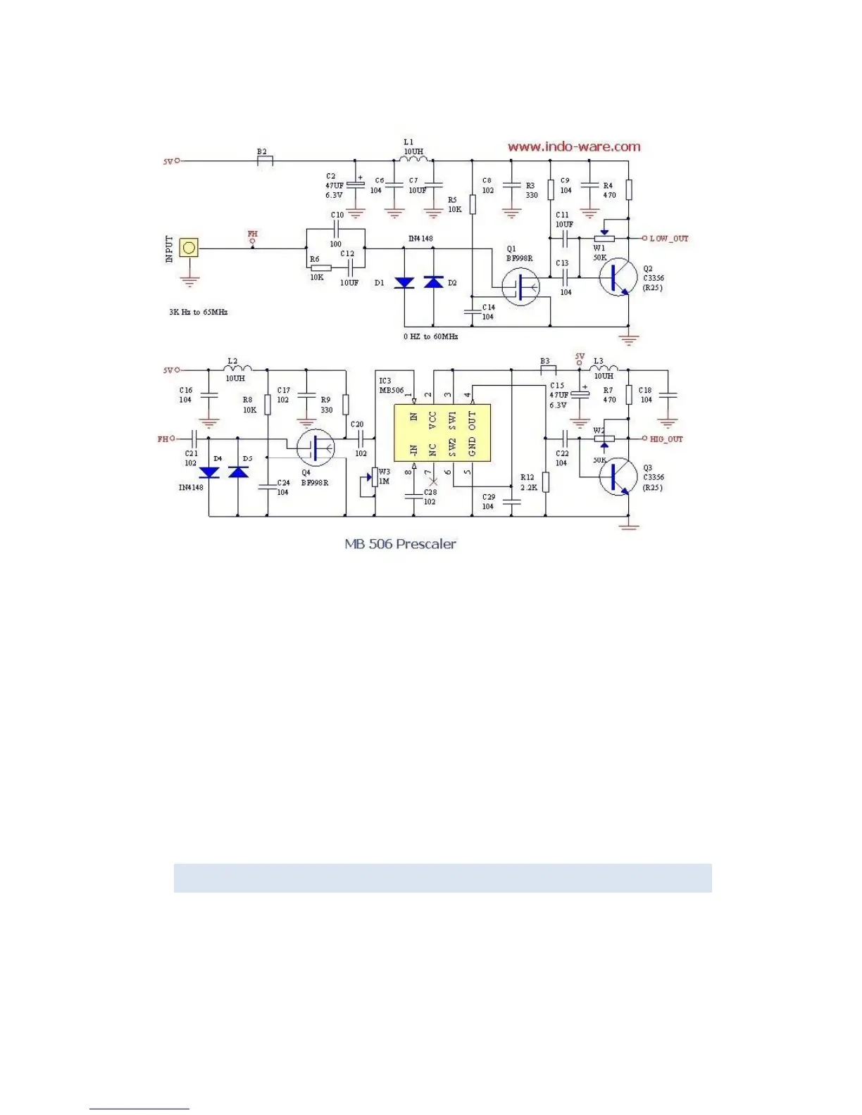
However, elsewhere, a circuit for the front end was located:
This shows a conventional preamplifier for each channel paralleled at the input, each channel using a
dual gate MOSFET as a preamplifier followed by a buffer stage (CH L) or divider/buffer (CH H). The
buffer transistors in each channel are used to obtain a TTL level. This somewhat “agricultural”
approach suggests that the low channel is likely to be excessively loading the higher channel, and that
is precisely what we see in the French sensitivity results.
The ideal solution to this is to separate out the two inputs and connect them to two separate input
connectors, one for each channel.
Note: The High channel (including prescaler) is located on the visible side of the PCB adjacent to the
PIC microprocessor and the TM1639 LED display driver. The Low channel is not visible. It is located
under the left hand front panel LED display (when the module is viewed from the front) and is
connected to the input connector and microcontroller via through-plated holes in the PCB.
4. CHANNEL SWITCHING RELIABILITY
The manual notes (See above) that the automatic channel switching does not always work reliably for
low frequencies above 30 MHz. In this case it is best to manually select the range.
For frequencies above 100 MHz, the hundreds digit may not be displayed sometimes. In this case,
press the Δ button to select the appropriate gate time until the hundreds digit is displayed.
 Loading...