PLJ-8LED Frequency Counter User Operating Manual 5
OPERATION AND USE
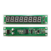
1. MODULE ARRANGEMENT
Front view of module
DC In TCXO cal Program Input sensitivity (H/L) RF In
Rear view of module
Note: This diagram shows the High channel (Ch H) components on the right hand end of the board.
The Low channel components are located on the other side of the PCB under the LED display.
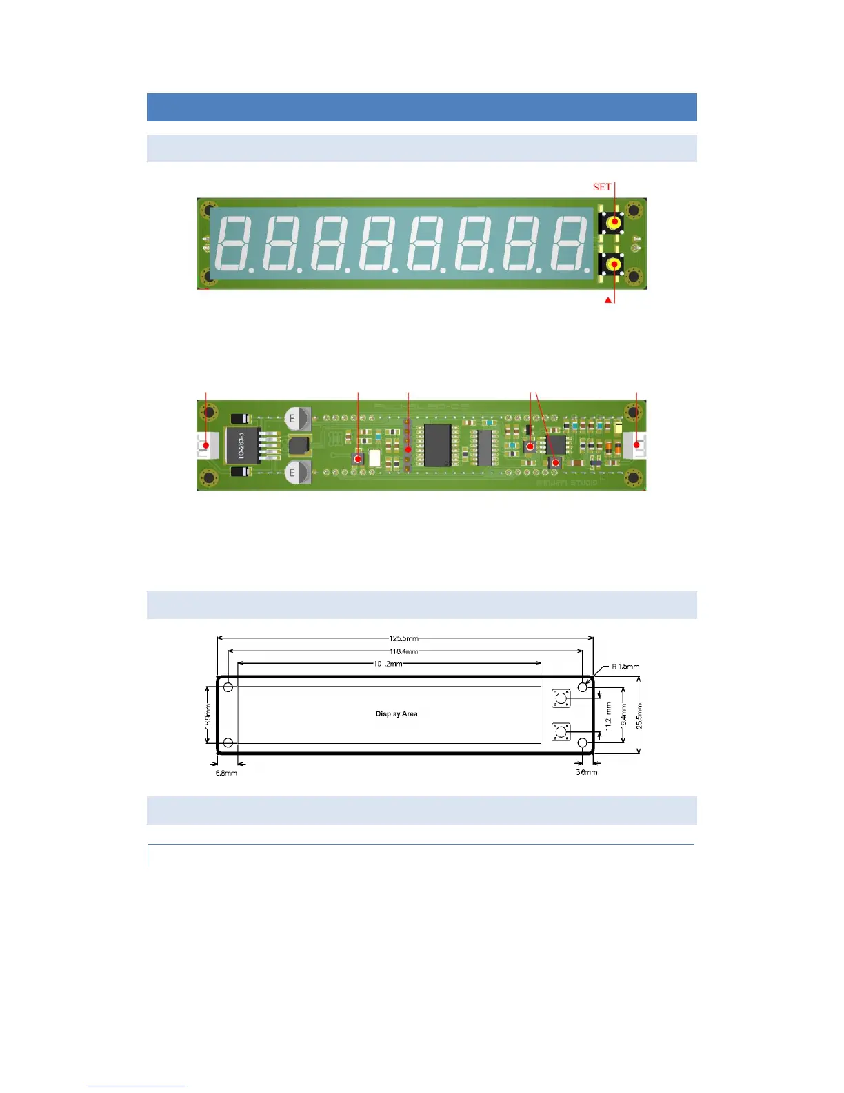
2. MOUNTING DIMENSIONS
3. USING THE MODULE
(A) PREPARATION
1. Please check the power supply voltage (DC 9V-15V) and confirm the power supply polarity before
use. The power supply circuit in the module has a series diode fitted to prevent operation when the
power supply is inadvertently connected with reverse polarity. This protects the module from
devastating consequences.
NOTE:
Check the Polarity of the Power & Input Pigtails: 1 Pigtail is Pinned for Power the other is
for the Signal Input CHECK THE SYMBOLS ON THE BOARD
Power:+Red/-Black Signal Input "S" Red /Gnd symbol Black
 Loading...