PLJ-8LED Frequency Counter User Operating Manual 8
SELECTION OF IF FREQ UENCY
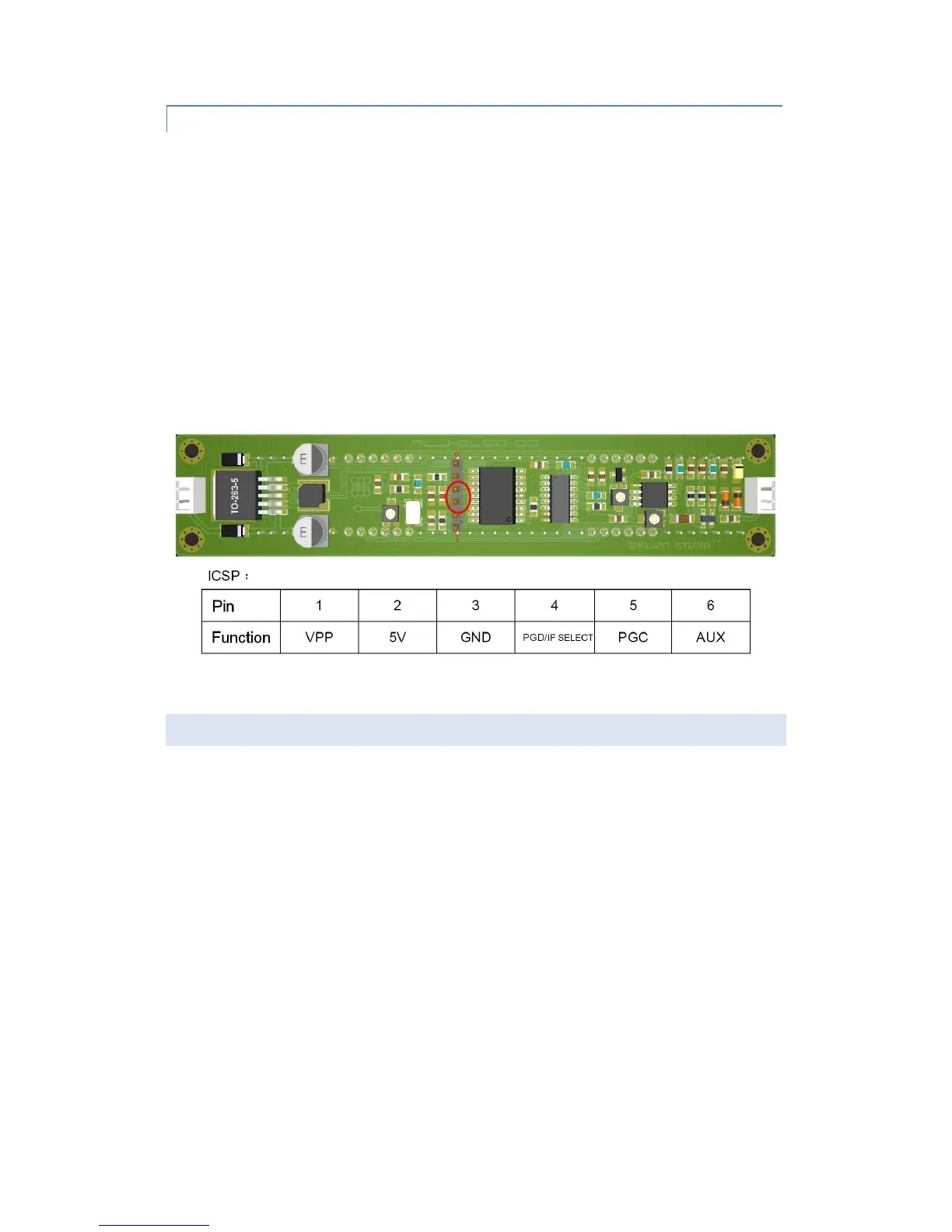
One of two IF frequencies may be selected by using pin 4 of the ICSP programming interface. If pin 4 is
pulled High or left floating, then the first IF frequency is used. If pin 4 is pulled to ground, then the
second IF frequency is selected.
Each IF frequency can be independently programmed with IF frequency and offset (Add or subtract).
The first IF settings are programmed when pin 4 is pulled High or left floating, and. the second IF
settings are programmed when pin 4 is pulled to ground.
The default factory programming sets the floating pin 4 as the first IF configuration. If the IF is zero,
then the Up/Down setting is ignored.
In practice, pin 3 (GND) and pin 4 of the ICSP programming interface ICSP can be connected to a 2P
DuPont connector immediately adjacent or on the pins (See location circled in red below). A switch
can then be connected to select the appropriate IF setting.
(C) MEASURING FREQUENCIES
The signal to be measured should be connected to the RF IN (signal input) port. This signal input can
be connected to the local oscillator output from a transceiver or to other test points. Once connected,
the LED display will show the frequency in real time.
The high-impedance input design helps to reduce the load of the counter on the local oscillator circuit
in the transceiver LO. However, the signal being measured should be greater than 60mVpp. For
example, the oscillator signal from the widely used NE602 / NE612 is weak and the counter may not
be able to obtain a stable frequency value.
 Loading...