Do you have a question about the SANJIANG JB-QGL-9100E and is the answer not in the manual?
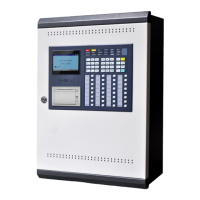
Introduces the fire alarm control panel and its applications.
Lists key features of the fire alarm control system.
Illustrates the wiring diagram of the fire alarm control panel system.
Details the main components of the fire alarm control system.
Lists the technical specifications including power supply and operating conditions.
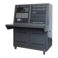
Shows the physical appearance and dimensions of the JB-QTL-9100E panel.
Provides steps and checks for installing the fire alarm control system.
Describes the procedure for performing a power-on test of the control unit.
Details checks for external devices and wiring connections.
Outlines the process of system commissioning including testing and setup.
Describes panel layout, indicators, and their meanings.
Explains the functions and usage of various buttons on the control panel.
Details the operation of specific panel buttons like AUTO/MANUAL, MUTE, TEST, RESET.
Explains the key switch function and the components of the LCD display.
Guides through system start-up and user login procedures with different roles.
Details how to log in and log out of the system using different methods.
Explains special function keys and their corresponding panel button actions.
Introduces the system setup sub-menus for configuration.
Describes how to set the system date and time.
Explains how to configure zones, buildings, and floors for the system.
Provides detailed steps for setting up zones, buildings, and floors.
Details how to configure the system for networking multiple panels via CAN bus.
Explains transmission rate, cable selection, and networking considerations.
Guides on setting and managing user passwords for different access levels.
Describes the setup for Fire Indicating Panels (FIP) and Extenders.
Explains the setup for Fire Indicating Panels connected via an extender.
Details how to configure the system's power supply monitoring.
Guides on setting up the system printer parameters.
Explains how to change the system's name.
Describes the function to automatically turn off the LCD after inactivity.
Introduces the sub-menus related to CAN-Bus configuration.
Details the configuration process for IO-Boards within the CAN-Bus system.
Guides on configuring detector and module properties and types.
Explains manufacturing types and output modes for detectors and modules.
Covers setting work modes and position descriptions for detectors/modules.
Details position description setup and row batch setup for devices.
Explains how to add new custom device types to the system.
Details column batch setup for configuring device properties in batches.
Introduces the sub-menus for configuring cause and effect (C&E) linkages.
Guides on setting up system-wide linkage conditions and outputs.
Explains detailed steps for setting up system linkages, including conditions and outputs.
Details delay time settings and input type selections for system linkages.
Covers setting fire quantity for linkages and selecting IO-boards.
Explains how to configure linkage conditions based on zones.
Details how to set up linkage conditions based on buildings.
Describes how to configure linkage based on floors, including type and point output.
Explains floor linkage setup for type output and point output.
Guides on setting up linkage conditions based on room ranges.
Explains how to configure complex linkages involving multiple detectors or modules.
Details the setup for manual control panels directly linked to modules.
Describes the setup for broadcast control panels and their points.
Explains how to set up broadcast points for controlling modules.
Details the correlation setup between fire hydrants and water pumps.
Introduces the sub-menus for operating the system.
Explains how to check for repeated device addresses in the loop.
Guides on performing single point tests for detectors/modules.
Describes how to start or stop individual points on the system.
Explains the auto-registration process for detectors and modules.
Explains how to disable current alarms.
Guides on querying currently disabled devices.
Describes how to cancel all disablement settings.
Explains how to query current delay times for linked equipment.
Introduces the function to query historical system events.
Guides on querying historical fault records.
Explains how to query historical linkage events.
Details how to query historical operation logs.
Describes how to delete historical records.
Introduces special operations for debugging and maintenance.
Guides on backing up system data to a USB drive.
Explains how to load system data from a USB drive.
Details how to check bus communication quality.
Describes the dangerous function to reset all system files.
Explains the statistical function for counting system elements.
Guides on adjusting the LCD brightness of the control panel.
Provides information about the system version and operating status.
Lists and describes different types of alarm messages displayed by the system.
Explains the components and information displayed on the alarm interface.
Details how to perform operations on the alarm interface like querying, disabling, silencing, and resetting.
Introduces the manual control panels and their functions.
Describes the multi-wire linkage units, their points, and wiring.
Addresses common issues like no alarm action, linkage problems, and printer errors.
Covers networking problems and loop short/open circuit issues.
Lists the available device types for the alarm equipment.
Continues listing device types and includes a statement about the manual's accuracy.
| Model | JB-QGL-9100E |
|---|---|
| Category | Control Panel |
| Power Supply | AC 220V ±10%, 50Hz |
| Alarm Power | ≤ 30W |
| Humidity | ≤95%RH(non-condensing) |
| Display | 7-inch LCD |