7
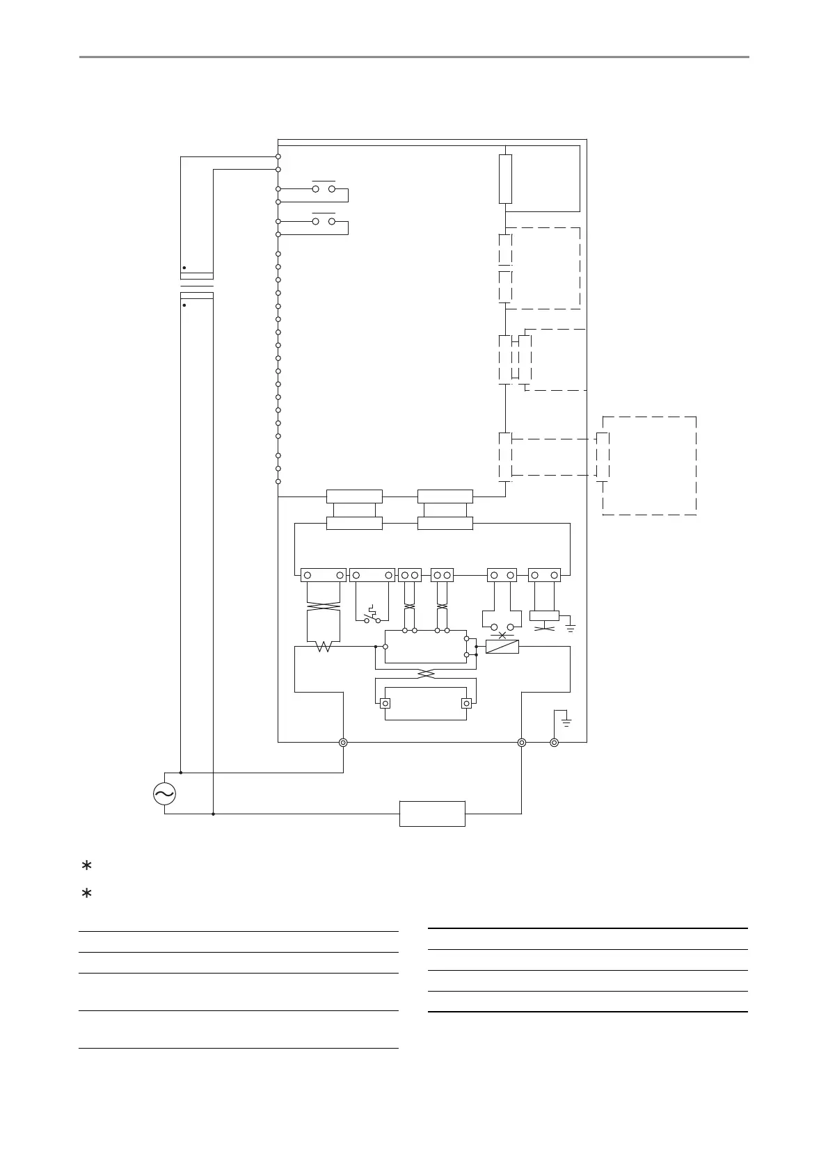
CONNECTION DIAGRAM OF UNIT
For wiring of the external input terminals, refer to the Connection Diagram for Each Setting System.
Use a transformer to obtain a 200/220V of the control power when other value of the power supply voltage is
supplied for the main circuit. Align the polarities between the main and control circuits for wiring.
LK
K2 K1
G2K2 G1K1
V1
D1
I1
VE1
VL2
VH2
VF2
VE3
PH
GT
ST
AT
RT
PS
-
S
+
HC
HA
1C
1A
0
200
HL
F1
TF1
FAN1
PCB1
PCB2
PCB4
CT1
THS1
CN2
CN3
CN1
CN5
UF-DP
THY1
+
-
UF-TB
UF-RS485
UF-DN
UF-CL
UF-PR
PCB3
Abnormality
indication
circuit
Conversion
Board
Display
panel
Communication
unit
Control circuits
Power supply, Gate circuit
Snubber circuit
Major failure
output
External
input and
output
terminals
Conversion
board
(option)
Minor failure
output
Power
supply
Load
THY1 Thyristor
FAN1 Cooling fan (forced air cooling only)
F1 Fuse
(only for models with the indication of F)
TF1 Fuse warning contact
(only for models with the indication of F)
CT1 Current transformer
PCB Printed circuit board
CN Connector
THS1 Thermal switch
 Loading...