CD-E770
E. How to Remove the Pickup Assembly (D
• Cautions when removing the pickup assembly: Solder the points
indicated in the figure before disconnecting the two lead connectors.
This protects the pickup from damage by static.
1.
Remove the tray damp arm.
2. Rotate the gear holder counterclockwise to remove the middle gear ®.
3.
Shift the supportrail stopper in the dirertion shown by the arrow in the
figure.
4.
Take out the support rail ® and remove the pickup assembly.
5. Disconnect the two leads running from the pickup assembly to the
F-6110
board.
• Cautions when renewing the laser pickup assembly:
1.
Connect the two lead connectors to the new pickup assembly.
2. Desolder the two points that were soldered to protect the device from
static.
F. How to Remove the Lift Arm
1.
Remove the tray ® and clamper arm ®.
2. Rotate the lift arm stopper clockwise (in the direction of the arrow)
then pull out the lift arm in the direction shown by the arrow.
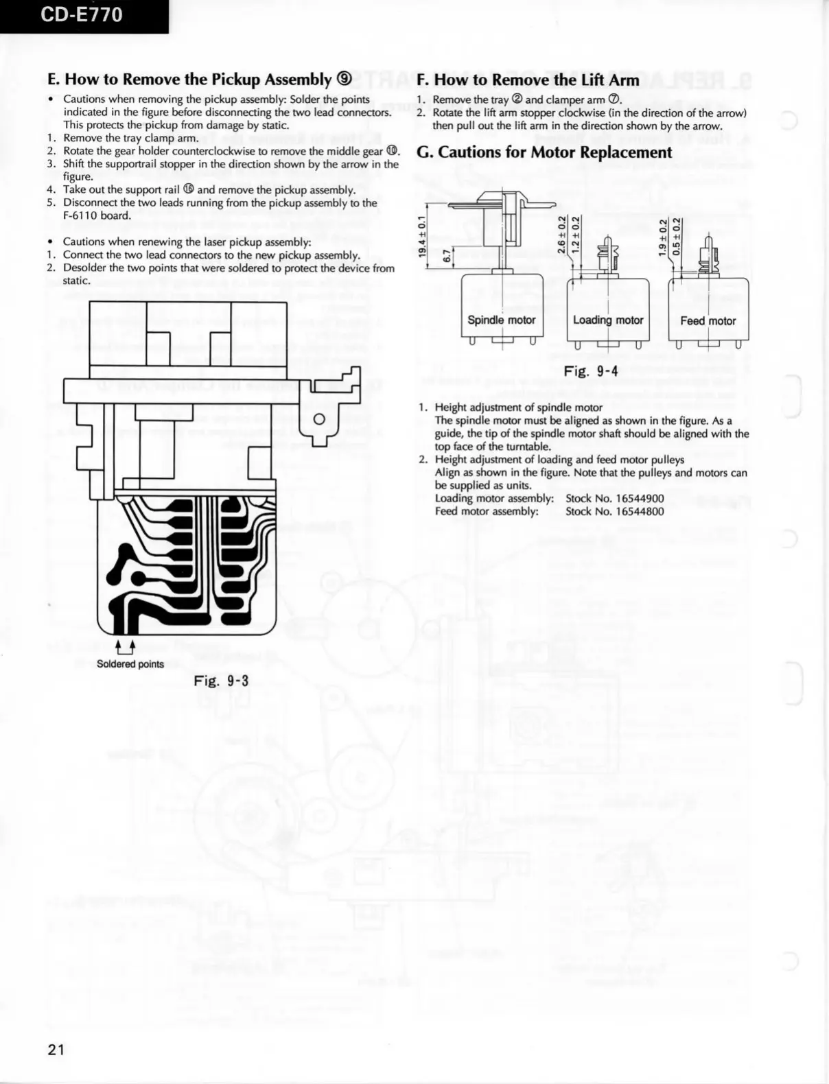
G.
Cautions for Motor Replacement
Ö
-H .
t ^
}
Loadini 3 motor
u H
-1 U
Fig.
9-4
1.
Height adjustment of spindle motor
The spindle motor must be aligned as shown in the figure. As a
guide,
the tip of the spindle motor shaft should be aligned with the
top face of the turntable.
2. Height adjustment of loading and feed motor pulleys
Align as shown in the figure. Note that the pulleys and motors can
be supplied as units.
Loading motor assembly: Stock No. 16544900
Feed motor assembly: Stock No. 16544800
D
Soldered points
Fig.
9-3
D
21
 Loading...