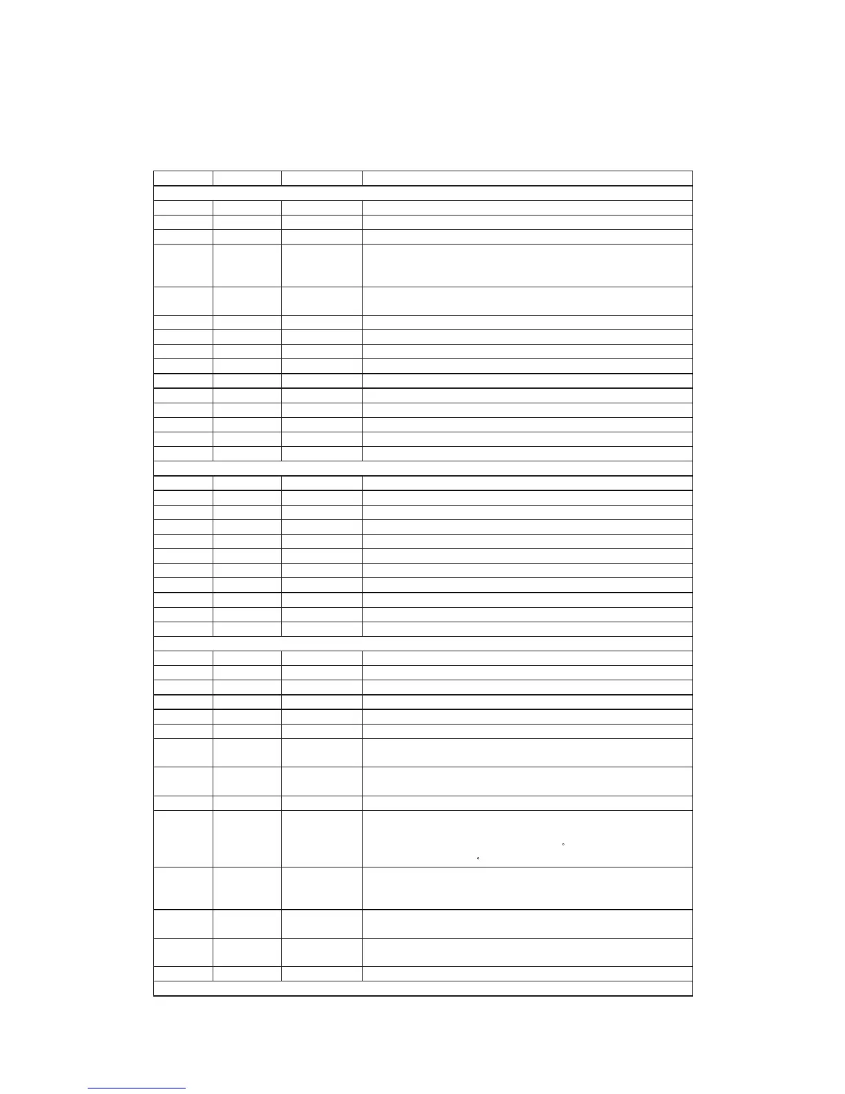
D1870 PIN ASSIGNMENTS
Pin Numbers Pin NAME Type Description
RG data PLL interface
11 PLLVDD Power Power for data PLL and related analog circuitry.
10 JITFN Analog Input The negative input term inal of operation amplifier for RF jitter meter.
9 JITFO Analog Output The output term inal of RF jitter meter.
8 PDO Analog Output
Phase com parator output. Output the phase difference of EFM and Pck4m.
Sink or source a constant current to loop filter over this pin when phase
difference occurs. Otherwise, this pin is high im pedance.
7 IREF Analog Input
Current reference input. It generates reference current for data PLL.
Connect an external 15K resistor to this pin and PLLVSS.
6 LPFN Analog Input The negative input term inal of loop filter am plifier.
5 LPFO Analog O utput The output of loop filter amplifier.
4 LPIN Analog Input The input of the low pass filter.
3 LPIO Analog O utput The output of the low pass filter.
2 PLLVSS Ground Ground pin for data PLL and related analog circuitry.
1 VBDPLL Analog Output Reference voltage.
176 RFIN Analog Input The negative input term inal of RF differential signal.
175 RFIP Analog Input The positive input term inal of RF differential signal.
174 RFDSLV Analog Output RF data slicer level output.
173 SCO Analog Output Analog slicer current output.
Signal Amplifier Interface
172 ADCVDD Power Power pin for ADC circuitry.
171 HRFZC Analog Input High frequency RF ripple zero crossing input or photo interrupt pulse input.
170 RFRPSLV Analog O utput RF ripple slice level output.
169 RFP Analog Input RF ripple detect input.
168 RFLEVEL Analog Input Sub beam add input or RF level input.
167 FEI Analog Input Focus error input.
166 TEI Analog Input Tracking error input.
165 TEZU Analog Input Tracking error zero crossing input.
164 TEZISLV Analog Input Tracking error zero crossing low pass input.
163 ADIN Analog Input General A/D input.
162 ADCVSS Ground Ground pin for ADC circuitry.
Motor and Actuator Drive Interface
161 PDMVSS G round G round for PDM Circuitry.
160 PWM2VREF Analog Input A reference voltage input for PWM circuitry. The typical value is 4.0V.
159 PWMVREF Analog Input A reference voltage input for PW M circuitry. The typical value is 2.0V.
158 PDMVDD Power Power for PDM circuitry.
12 FOO Analog Output Focus servo output. PDM output of focus servo compensator.
13 TRO Analog Output Tracking servo output. PDM output of tracking servo com pensator.
14 PWMO UT1 Analog O utput
1 s t General multi-level PW M output . T he n umber of output level s i s s et
with DSP com mand. It is used to control step motor.
15 PWMO UT2 Analog O utput
2 nd G eneral m ulti-level PW M output. The number of output level is
selected DSP comm and.
17 DMO Analog Output Disk m otor control output. PWM output.
18 FMO Analog Output
Disk m otor control. 3-level PWM output. It is used o nly for DC motor, but it
is corporate with the pin PWMOUT1 to control step m otor. If the internal
DC_FMO i s positive, t he FMO output l ags 90
than PWMOUT1, otherwise
the FMO output leads 90
than PW MO UT1.
19
FROPENPW
M
Analog Output
Tray open control output.
It generates PW M output for TRWMEN
27hRW 2
=0 or digital output for
TRW MEN
27hRW 2
=0.
20 FG
TTL Schmitt
Input 50K pull up
Motor Hall sensor input.
22 TRCLOSE TTL O utput
Tray close output.
It provides a clock out to the micro controller.
23 ENDM TTL Output Enable/disable disk motor. A logical high enables disk m otor.
Panel Interface
9
 Loading...