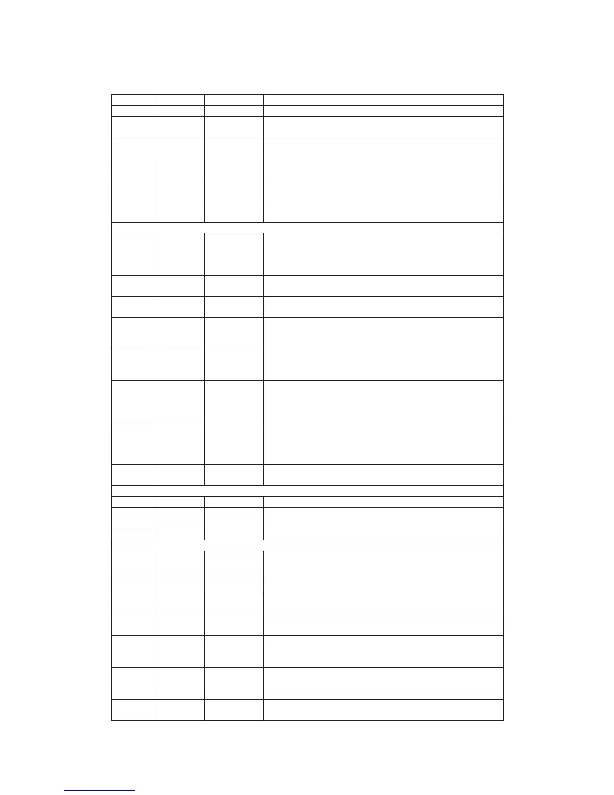
Pin Numbers Pin NAME Type Description
24 LED TTL O utput LED control output.
25 PLY#/PAU#
TTL Input
50K pull up
Play/pause key input, active low.
26 EJ/STOP#
TTL Input
50K pull up
Eject, stop key input, active low.
27 LIMIT#
TTL Input
50K pull up
Sledge inner limit input, active low.
28 TRAYOUT#
TTL Input
50K pull up
Tray_is_out input. A logical low indicates the tray is out. Feedback flag
from tray connector.
29 TRAYIN#
TTL Input
50K pull up
Tray_is_in input. A logical low indicates the tray is in. Feedback flag from
tray connector.
Micro controller Interface
30 URST TTL Output
Power-on reset output for external devices, active high.
If the flash mode is used, the micro controller m ust be the kind of
multiplexed address/data mode and its output pins m ust be at tri-state.
Otherwise, the flash m ode cannot be used.
31 UWR#
TTL Schmitt
Input 50K pull up
Micro controller write strobe, active low.
32 URD#
TTL Schmitt
Input 50K pull up
Micro controller read strobe, active low.
33 UCS1
TTL I/O
50K pull up
For non flash mode cycle: register bank select control 1, input from m icro
controller.
For flash m ode cycle: flash ROM address FLASH_ADR14.
34 UCS2
TTL I/O
50K pull up
For non flash mode cycle: register bank select control 2, input from m icro
controller.
For flash m ode cycle: flash ROM address FLASH_ADR15.
36 UALE
TTL I/O
with Schmitt
Input
50K pull up
For non flash mode cycle: address latch enable, high active input from
m icro controller.
For flash m ode cycle: address latch enable, high active output to control
external 373.
37-43,46 UAD
TTL I/O
50K pull up
For non flash mode cycle: micro control address/data Bus.
For flash m ode cycle: flash RO M address/data bus.
FLASH_ADR[7:0]/FLASH_D[7:0]. The FLASH_ADR[7:0] is latched in the
external 373.
47 UINT#
TTL Output
Open drain
Micro controller Interrupt, low active.
Crystal Interface & DRAM clock Interface
44 DMVSS Ground Ground pin for DRAM clock circuitry.
45 DMVDD Power Power pin for DRAM clock circuitry.
48 XTALI Input Crystal input. The working frequency in 33.8688MHz.
49 XTALO Output Crystal output.
Memory Interface
50 DQM TTL Output
For non flash mode: SDRAM output Mask.
For flash m ode: flash RO M address FLASH_ADR13.
51 BA1 TTL Output
For non flash mode: SDRAM bank address 1
For flash m ode: flash RO M address FLASH_ADR12.
52 BA0 TTL Output
For non flash mode: SDRAM bank address 0
For flash m ode: flash RO M address FLASH_ADR11.
53 CKE TTL Output
For non flash mode: SDRAM clock enable.
For flash m ode: flash RO M address FLASH_ADR10.
54 CLK TTL O utput SDRAM clock
55-56 RA[11:10] TTL O utput
For non flash mode: DRAM address bus RA[11:10]
For flash m ode: flash ROM address FLASH_ADR[9:8]
58-64,66-6
7,69
RA[9:0] TTL Output RAM address bus
70 RAS# TTL O utput RAM row address strobe, low active
71 ROE# TTL Output
RAM output enable, low active.
It must be pulled with 20K resister if flash mode is used.
10
 Loading...