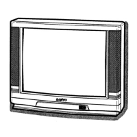
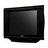
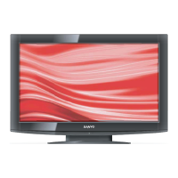
This document provides a comprehensive service manual for Sanyo Colour Televisions, specifically covering models with Mascot Numbers 28DN1, 25DN1, and 21DN1, all based on the EB4-A chassis. The manual details the function, technical specifications, usage, and maintenance of these television receivers.
Function Description
The Sanyo Colour Televisions are designed to receive and display television broadcasts. They incorporate a range of features to ensure high-quality audio and video output. The core functionality is managed by the main processing unit (CPU), which interacts with various sub-systems for signal processing, video output, audio output, and user control.
The television system supports System I and PAL colour standards, receiving UHF channels 21-69. It includes an AV terminal with 21 Pin sockets, adhering to the CENELEC standard, allowing for external audio and video input.
The internal architecture comprises several key blocks:
- Tuner: Receives broadcast signals.
- SIF Unit: Processes sound intermediate frequency signals.
- Audio Unit: Handles audio signal processing.
- IF/Video/Chroma/Def. (IC201): This integrated circuit is central to signal processing. It takes the IF output from the tuner, processes it through IF amplifier, video detection, and video amplifier circuits, outputting a composite video signal. It also handles sync separation, horizontal oscillation, and vertical drive signal generation.
- Vert. Output (IC501): Drives the vertical deflection coils of the CRT.
- Audio Output (IC001): Amplifies audio signals to drive the speakers.
- CPU (IC801): The central processing unit, responsible for overall control, including user input (control keys, remote control), memory management (IC802), and interfacing with other ICs for various functions like brightness, contrast, colour, and sharpness adjustments.
- Memory (IC802): Stores operational data and settings.
- Converter Transformer (T611): Part of the power supply circuit, converting AC input to various DC voltages required by the TV components.
- FBT (Flyback Transformer): Generates high voltage for the CRT and horizontal deflection signals.
- CRT Unit: The cathode ray tube, responsible for displaying the image.
The video processing chain involves separating luminance (Y) and chroma signals, demodulating chroma into R-Y and B-Y, and then processing these signals through an RGB matrix and selector. The system supports both internal and external RGB signals, with fast switching capabilities for mixed RGB modes and blanking functions.
Audio processing involves taking signals from the audio unit, passing them through pre-amplifier and drive circuits, and then through an audio amplifier (SEPP OTL type) to directly drive the speakers.
Important Technical Specifications
The televisions operate on an AC 220-240V, 50Hz power source.
C28EH65NB (28-inch model) Specifications:
- Sound output (Music): 12 watts X2
- Picture tube: 70cm diagonal, 110 degree deflection
- Visible picture diagonal: 66cm
- Dimensions (WxHxD): 740 x 585 x 494mm
- Weight: 31.6 Kg
C25EG65NB (25-inch model) Specifications:
- Sound output (Music): 12 watts X2
- Picture tube: 63cm diagonal, 110 degree deflection
- Visible picture diagonal: 59cm
- Dimensions (WxHxD): 680 x 535.5 x 449.5mm
- Weight: 25.5 Kg
C21EF45NB (21-inch model) Specifications:
- Sound output (Music): 9 watts X2
- Picture tube: 55cm diagonal, 90 degree deflection
- Visible picture diagonal: 51cm
- Dimensions (WxHxD): 596 x 465.5 x 483mm
- Weight: 21.5 Kg
Common Specifications:
- Power source: AC 220-240V 50Hz
- Television system: System I
- Colour system: PAL
- Receiving channel: UHF 21-69
- Aerial input impedance: 75ohm
- AV terminal: 21 Pin sockets (CENELEC standard)
Usage Features
The televisions offer user control over various picture and sound settings:
- Picture Controls: Brightness, Contrast, Colour, and Sharpness can be adjusted.
- Sound Controls: Bass, Treble, Balance, and Volume are adjustable.
- Functionality: Includes functions for AV input selection (AV1/AV2) and band switching.
- Text Brightness: A dedicated control for text display brightness.
Maintenance Features
The service manual outlines critical safety precautions and detailed adjustment procedures for technicians.
Safety Precautions:
- Isolation Transformer: An isolation transformer must be used when servicing the primary side of the converter transformer to prevent electrical shock.
- Safety-Related Notes: All caution and safety-related notes on the cabinet, inside the cabinet, on the chassis, or the picture tube must be complied with.
- Protective Devices: When replacing a chassis, all protective devices (knobs, covers, shields, barriers, isolation resistor-capacitor networks) must be properly installed to ensure safe operation.
- X-RADIATION Precaution: The picture tube is the primary source of X-RADIATION. Only replacement tubes of the same type, including suffix letter, should be used. High voltage must be maintained within specified limits. Adjustments for +B1 volt power supply and high voltage are critical to prevent hazardous X-RADIATION.
Service Control Adjustments:
The manual provides step-by-step instructions for various adjustments, typically performed by a service technician:
- B1 Power Supply Adjustment: Involves setting VR641 to its mechanical centre, tuning to a PAL circular pattern, setting brightness and contrast to normal, and adjusting voltage at test point "TP-B" to specified values (130 ± 0.5 V for 21-inch models, 150 ± 0.5 V for 25-inch and 28-inch models).
- AFT Adjustment: Tuning to the clearest station and adjusting T141 for the best picture.
- AGC Adjustment: Adjusting AGC VR (VR130) until snow noise disappears, but not with a weak signal.
- High Voltage & Width Adjustment: Tuning to a circular pattern, setting brightness and contrast to maximum, connecting a V-meter to R224, and a high voltage meter to the CRT anode. Confirming high voltage to be within specified limits (25.0 ± 1 KV for 21-inch, 26.0 ± 1 KV for 25-inch and 28-inch models). H-width adjustment involves connecting/disconnecting J213 (for 21-inch) and adjusting VR462.
- Grey Scale Adjustment: Includes SCREEN VR adjustment (tuning to white pattern, setting brightness/contrast to normal, setting VR2601/VR2611 to mechanical centre, turning VR2602/VR2612/VR2622 fully anti-clockwise, entering service mode to highlight "SCREEN", and adjusting screen VR until one colour is just visible). BIAS VR adjustment (using VR2602/VR2612/VR2622 to make the line white). DRIVE VR adjustment (using VR2601/VR2611 for white balance).
- H-Centre Adjustment: Tuning to circular pattern and adjusting H-centre using VR361.
- V-Centre Adjustment: Tuning to circular pattern and adjusting V-centre using SW501.
- V-Size Adjustment: Tuning to circular pattern and adjusting V-size using VR501.
- Focus Adjustment: Adjusting FOCUS VR for good scanning lines.
Circuit Alignment:
Detailed procedures for VIF, Trap, and SIF alignment are provided, including settings for DC voltage, AGC voltage, output probe, input probe, marker frequency, and sweep ATT, along with expected waveforms.
Initialisation (Important Notice):
When replacing the memory IC (IC802), it must be initialised. This involves pressing and holding the normalisation button on the remote control and the programme + button on the TV set. This automatically sets default user control data (e.g., Colour, Brightness, Contrast to Centre/Maximum) and service data (K1, K2, ST ID, ATT). The manual specifies that K1, K2, ST ID, and ATT are invalid adjustments for these models and have no effect, despite being alterable.
Service Mode:
To enter service mode, press and hold the Function button on the remote control and the programme + button on the TV set. The OSD will display adjustable items (K1, K2, ST ID, ATT, SCREEN, VOL, CPU Ver). Items can be selected using the Function button and data changed using Level + or - buttons. To exit, press the Recall button.
Parts Lists:
The manual includes comprehensive cabinet parts lists for each model (C28EH65NB, C25EG65NB, C21EF45NB) and detailed electrical parts lists for the chassis, including capacitors, resistors, transistors, integrated circuits, coils, transformers, diodes, and miscellaneous components. Parts marked with /!\ are safety-critical and must be replaced with designated parts from the list.
Chassis Construction:
The document also lists the various Printed Wiring Board (PWB) assemblies that make up the chassis, such as Main PWB, SIF PWB, Audio PWB, and CRT PWB, along with their respective part numbers and the pages where their detailed parts lists can be found. Different service reference numbers correspond to different PWB configurations.