-9-
Service Adjustments with Replacing Memory IC(IC801)
(/JE0356B)
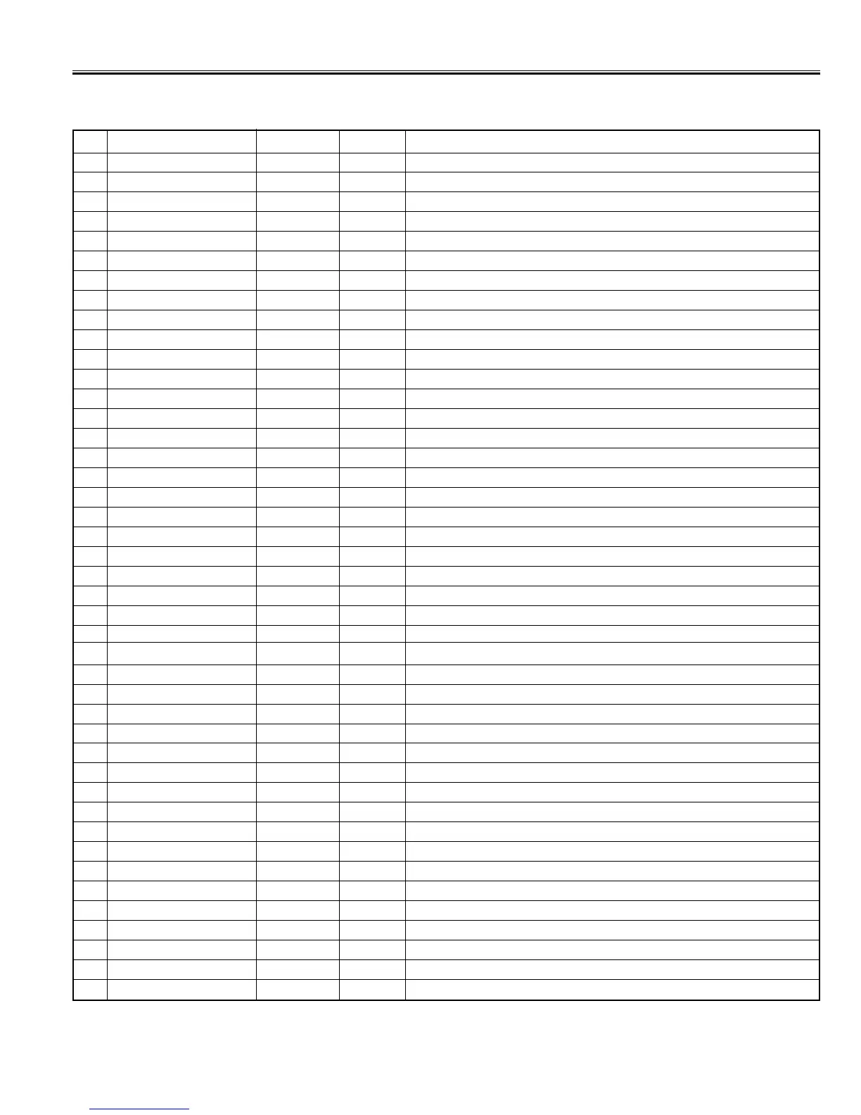
Following table shows the initial values which have been stored in the CPU ROM, and items for the service adjustments.
Service mode adjustments table in CPU ROM
No. Item Range Data Description
00 T-DIS 0 ~ 1 1 Disable the Test SW & enable Audio / Video Mute SW
01 HFREQ 0 ~ 7F 40 Align ES Sample horizontal frequency (MP is adjusted in the wafer line.)
02 AFC G 0 ~ 1 0 Select horizontal first loop gain & H-sync gating on/off
03 AMUTE 0 ~ 1 0 Disable audio outputs
04 VMUTE 0 ~ 1 0 Disable video output
05 H PHA 0 ~ 1F 0A Align sync to fly back phase
06 VS275 0 ~ 1 0 Enable 75% vertical size mode
07 VSIZE 0 ~ 7F 40 Align vertical amplitude
08 SKILL 0 ~ 1 0 Force free-run mode
09 VKILL 0 ~ 1 0 Disable vertical mode
10 V DC 0 ~ 3F 28 Align vertical DC bias
11 V SEP 0 ~ 1 0 Select vertical sync. Separation sensitivity
12 V RES 0 ~ 1 0 Select Vertical Reset Timing
13 HLOCK 0 ~ 1 0 Select Vertical sync system
14 VNSYN 0 ~ 1 0 Enable IC Test Mode
15 VSIFT 0 ~ F 5 Align vertical position
16 HBL 0 ~ 7 4 Left H-Blanking Control
17 V LIN 0 ~ 1F 12 Align vertical linearity
18 HBR 0 ~ 7 4 Right H-Blanking Control
19 V SC 0 ~ 1F 14 Align vertical S-correction
20 VTEST 0 ~ 3 0 Select vertical DAC test mode
21 VCOMP 0 ~ 7 7 Align vertical size compensation
22 CDMOD 0 ~ 7 0 Select vertical countdown mode
23 VIL T 0 ~ 1 0 Vertical deinterlace SW
24 VILT2 0 ~ 1 0 Vertical deinterlace SW2
25 VBLKS 0 ~ 1 1 V blanking control SW
26 FBPSW 0 ~ 1 1 Select Horizontal blanking operation
27 AFCNG 0 ~ 1 0 Enable AFC Low gain mode
28 AFC2S 0 ~ 1 0 Select FBP storage-timer tolerance level
29 CRSBW 0 ~ 3 0 Service Test Mode (normal/Cross/Black/White)
30 DEINT 0 ~ 1 0 Deinterlace
31 OETST 0 ~ 1 0 O/E.TEST
32 RBIAS 0 ~ FF 0 Align Red OUT DC level
33 GBIAS 0 ~ FF 0 Align Green OUT DC level
34 BBIAS 0 ~ FF 0 Align Blue OUT DC level
35 RDRV 0 ~ 7F 40 Align Red OUT AC level
36 GDRV 0 ~ 7F 40 Align Green OUT AC level
37 BDRV 0 ~ 7F 40 Align Blue OUT AC level
38 (One Line) 0 ~ 7F - White Balance
39 RD xx GD xx BD xx 0 ~ 7F 40 White Balance
40 BLDEF 0 ~ 1 0 Disable RGB output blanking
41 SUBBI 0 ~ 7F 38 Align common RGB DC level
42 VTRNS 0 ~ 1 1 Enable data transmission between vertical retrace period
 Loading...