— 9 —
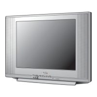
FOCUS ADJUSTMENT
1. Connect a color-bar generator to the antenna terminals
and select a crosshatch pattern.
2. Set the picture controls to the Sports levels.
3. Select a vertical line at the center of the screen and
adjust the H focus control for best focus.
4. Select a horizontal line at the top of the screen and
adjust the V focus control for best focus.
5. Repeat steps 3 and 4 for best focus.
SOUND ADJUSTMENT
1. Connect a color-bar generator to the antenna terminals
with audio signal of 1KHz at 100% modulation.
2. Set the picture controls to the Sports levels
3. Connect oscilloscope + lead to TP21 (pin 75 of IC101)
and – lead to ground.
4. Turn off the receiver and disconnect the AC power cord
(AC 120V line).
5. While pressing the Menu key, reconnect the AC power
cord. The Service Menu will now appear.
6. Select NO. 45 FL (FM Level) with the ▲ or ▼ key.
7. Adjust the data with the + or – key for an oscilloscope
reading of 0.693 ± 10% VP-P at TP21.
8. Press the MENU key to turn off the Service Menu display
and disconnect the oscilloscope from the chassis.
MULTI-SOUND SECTION ADJUSTMENTS
Note: Multi-Sound Section must be adjusted after
IC101 (Signal Processor), IC3401 (MTS Decoder), or
IC802 (EEPROM) is replaced.
INPUT LEVEL ADJUSTMENT
1. Connect a signal to the antenna terminals with audio of
1 KHZ 100% modulation.
2. Turn off the receiver and disconnect the AC power cord
(AC 120V line).
3. Connect voltmeter (RMS) to TP317 and ground.
4. While pressing the Menu key, reconnect the AC power
cord. The Service Menu will now appear.
5. Select NO. 60 ATT (Attenuation) with the ▲ or ▼ key.
6. Adjust the + or – key for a voltmeter reading of 400 ± 20
mVrms at TP317.
SEPARATION ADJUSTMENT
7. Turn off the receiver and disconnect the AC power cord
(AC 120V line).
8. Connect oscilloscope CH1 to TP317 and CH2 to TP318
and ground.
9. Connect an MTS TV/Stereo generator to antenna terminal.
10. While pressing the Menu key, reconnect the AC power
cord. The Service Menu will now appear.
11. Select pilot, 300Hz audio frequency and Left modulating
signal.
12. Select NO. 61 WDB (Wideband) with the ▲ or ▼ key.
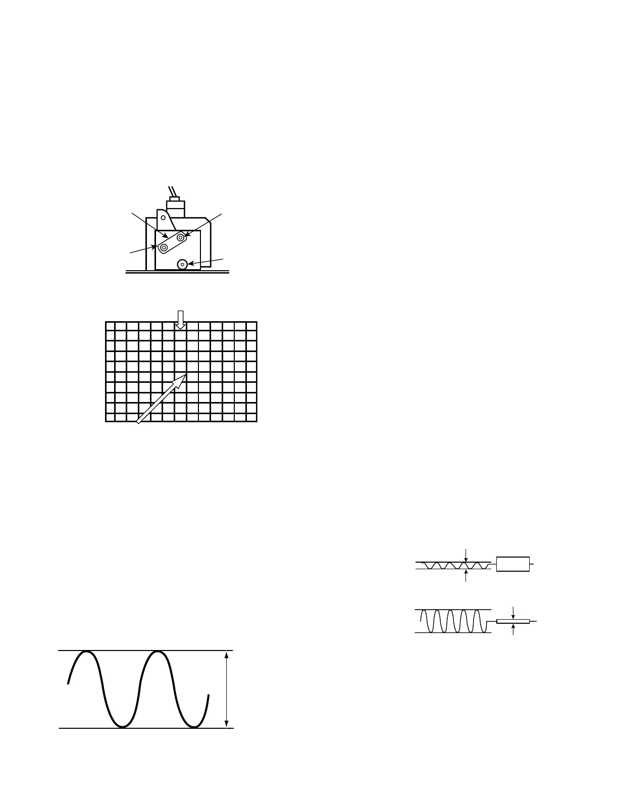
13. Adjust the + or – key for minimum low frequencies at
TP317. (See Figure 10.)
14. Select 4 KHz audio frequency and Right modulating signal.
15. Select NO. 62 SPC (Spectral) with the ▲ or ▼ key.
16. Adjust the + or – key for minimum high frequencies at
TP318. (See Figure 10.)
Repeat adjustments (steps 11–16) until no further decreases
in amplitude can be obtained. Press the MENU key to turn
off the Service Menu display.
PURITY AND CONVERGENCE ADJUSTMENTS
Purity and Convergence have been aligned at the factory.
No re-alignment is necessary.
 Loading...