J
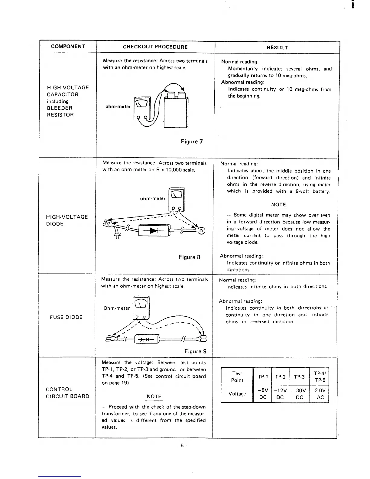
COMPONENT
CHECKOUT procedure
RESULT
Measure the resistance: Across two terminals
Normal reading:
with an ohm-meter on highest scale.
Momentarily indicates several ohms, and
gradually returns to 10 meg-ohms.
Abnormal reading:
HIGH-VOLTAGE
CAPACITOR
Indicates continuity or 10 meg-ohms from
Wfi
~
the beginning.
including
BLEEDER
ohm-meter
Q
RESISTOR
Figure
7
Measure the resistance: Across two terminals
Normal reading:
with an ohm-meter on R x 10,000 scale.
Indicates about the middle position in one
direction (forward direction) and infinite
ohms in the reverse direction, using meter
/
m
which is provided with a 9-volt battery.
ohm-meter
6Y
NOTE
HIGH-VOLTAGE
– Some digital meter may show over even
DIODE
“0 ;--m&
in a forward direction because low measur-
ing voltage of meter does not allow the
meter current to pass through the high
voltage diode.
Figure
8
Abnormal reading:
Indicates continuity or infinite ohms in both
directions.
Measure The resistance: Across two terminals
Normal reading:
with an ohmmeter on highest scale.
Indicates infinite ohms in both directions.
/
A
m
Abnormal reading:
Ohm-meter
Indica[es continuity in both directions or
FUSE DIODE
continuity in one direction and
infinite
ohms in reversed direction.
Figure 9
Measure the voltage: Between test points
TP-1, TP-2, or TP-3 and ground or between
TP-4 and TP-5. (See control circuit board
Test
TP- 1
TP-2
TP-3
TP-4/
on page 19)
Point
TP.5
CONTROL
-5V
–12V –30V
CIRCUIT BOARD
Voltage Dc
2.OV
NOTE
DC DC
AC
4
- Proceed with the check of the step-down
transformer, to see if any one of the measur-
ed values is different from the specified
values.
–5-
 Loading...