‘..
-.
.-,.
.
COMPONENT
I
TOUCH KEY
BOARD
CHECKOUT PROCELURE
—
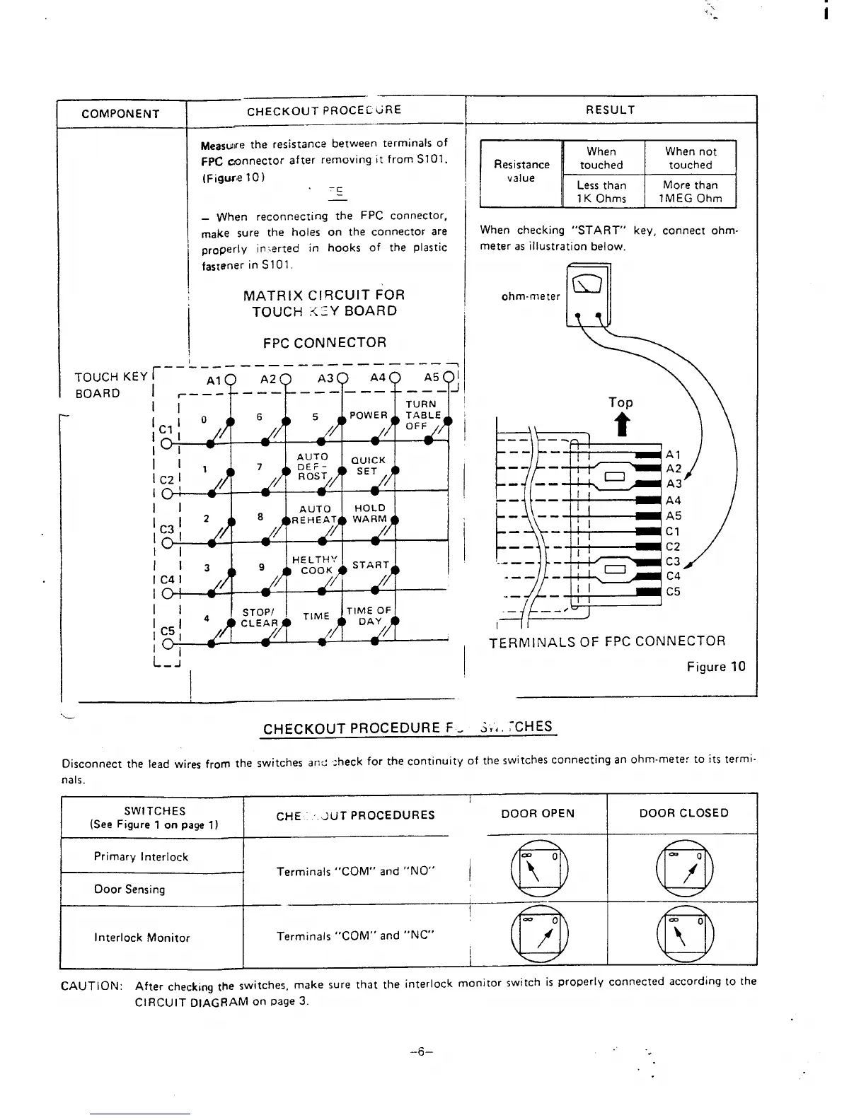
Measwre the resistance between terminals of
FpC connector after removing it from S101.
(Figure 10)
-c
—
When reconnecting the FPC connector,
make sure the holes on the connector are
properly in~erted
in hooks of the plastic
fastener in S101.
MATRIX CIRCUIT
FOR
TOUCH KEY BOARD
FPC CONNECTOR
.——
---- ——
——— ——
——— ——. —
7
I
0
6 5
POWER
TABLE
c1 /
OFF
01
.
-
11
AUTO
7
)
DE F-
QUICK
IC21
1
ROST
SET
10!
I
I
w
II
AUTO
HOLD
112
8
)
WARM
10
C3 ,
/
.
.
w
w
;13
9
HE LTH’.’
y
/ ‘
/’/f
COOK
START
IC41
10:
.
I
II
STOPI
I
TIME
JTIME oF
4
CLEAR
DAY
;C5;
lo
A
w
L_;
.
!
RESULT
Resistance
value
M
When checking “START” key, connect ohm-
meter as illustration below.
ohm-meter
FEES
Al
A2
A3
)
TERMINALS OF FPC CONNECTOR
Figure 10
‘C-
HECKOUT PROCEDURE F. S,’, ‘CHES
Disconnect the lead wires from the switches anc :
heck for the continuity of the switches connecting an ohm-meter to its termi-
nals.
I
SWITCHES
(See Figure 1 on page 1)
CHE .JUT PROCEDURES
DOOR OPEN
DOOR CLOSED
Primary Interlock
Terminals “COM” and “NO”
Door Sensing
!0
Q
Interlock Monitor
Terminals “COM” and “NC”
;Q
Q.
CAUTION: After checking the switches,
make sure that the interlock monitor switch is properly connected according to the
CIRCUIT DIAGRAM on page 3.
–6–
‘.
 Loading...