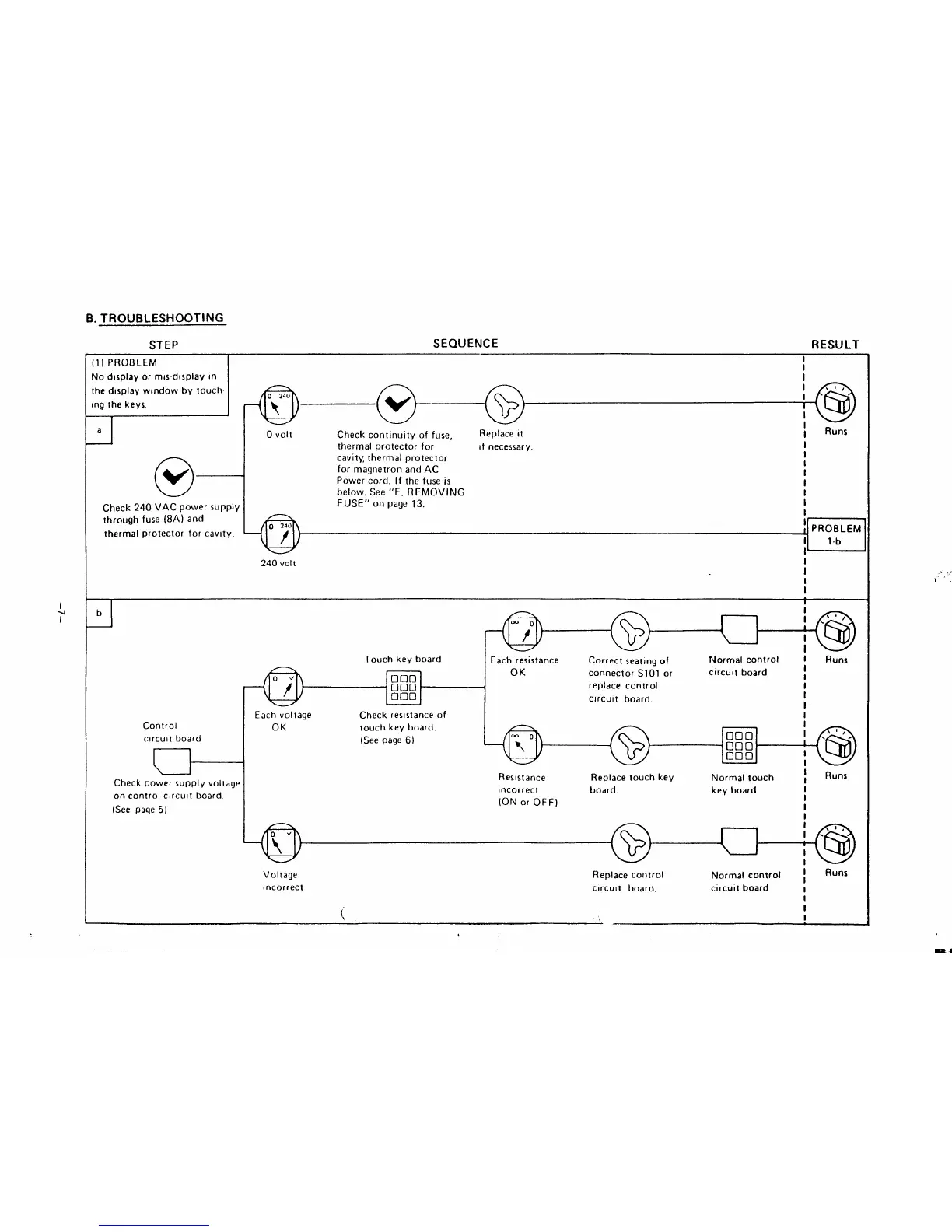
B. TROUBLESHOOTING
STEP
SEQUENCE
RESULT
J
(1) PROBLEM
Nodlsplayormis-display (n
Ihedlsplay wlndowby touch-
ing the keys.
al
o
v
Check 240 VAC power supply
through fuse (8A) and
thermal protector for cavity.
I
I
I
-cl
I
O 240
,t,
f
@
I
I
@
I
o
Voll
Check continuity of fuse,
Replace it
I
Runs
thermal protector for If necessary.
I
cavity, thermal protector
I
for magnetron and AC
I
Power cord. If the fuseis
I
I
below. See “F. REMOVING
I
FUSE” on page 13.
I
I
[ PROBLEM
I
lb
1’
240 volt
I
I
I
1
I
1
J
b
Touch key board
.
nom
000
‘
000
Control
c!rcult board
t
Check powe~ supply voltage
on control circuit board
(See page 5)
Each voltage
Check resistance of
OK
touch key board.
(See page 6)
I
(Q
I ,’”
I
‘(6J
I
Each resistance Correct seating of
Normal control I
OK
connector S101 or
circuit board
I
I
replace control
I
circuit board,
I
I
I
Runs
,
I
1=
\a,
@
000
000 ‘
000
I
‘@
I
Resistance
Replace touch key Normal touch
I
I
Runs
Incorrect
board.
key board
(ON or OFF)
/
I
I
I
@
I .’”
I
‘@
I
Voltage Replace control
Normal control ~
Runs
tincorrect
circuit board, circuit board
I
I
i
I
‘,
I
.(,
1“’.
 Loading...