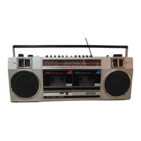
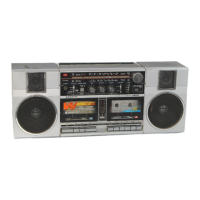
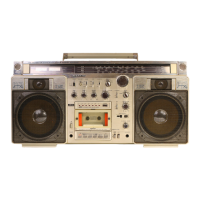
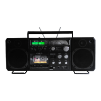
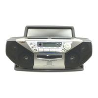
The Sanyo M W200L is a portable cassette recorder designed for both recording and playback, featuring a dual-cassette mechanism for convenient tape-to-tape dubbing. This model is specifically designed for the European market, as indicated by the "EUROPE" designation.
Function Description
The primary function of the M W200L is to record and play back audio on cassette tapes. It supports stereo recording and playback, utilizing an AC bias and 4-track stereo recording system, with a 2-track AC erase system. The dual-cassette design allows for high-speed dubbing, enabling users to copy tapes quickly. In addition to its cassette functions, the device incorporates a multi-band radio tuner, capable of receiving LW (Long Wave), MW (Medium Wave), SW (Short Wave), and FM (Frequency Modulation) broadcasts. Audio output is provided through built-in speakers, and there are provisions for external speakers and headphones. An external microphone input is also available for recording from an external source.
Important Technical Specifications
- Recording System: AC bias, 4-track stereo
- Erasing System: AC erase, 2-track
- Tape Speed: 4.75 cm/sec (1-7/8 i.p.s.)
- Rewind and Fast Forward Time: Approximately 2 minutes for a C-60 cassette
- Frequency Range (Radio):
- LW: 150 - 285 kHz
- MW: 525 - 1,605 kHz
- SW: 5.95 - 18 MHz
- FM: 87.5 - 108 MHz
- Terminal Impedance:
- EXT.MIC: 22k ohms (1 mV)
- EXT SP: 4 - 8 ohms
- HEAD PHONE: 32 ohms
- Frequency Response (Cassette): 90 - 13,000 Hz
- Output Power: 4 W (maximum)
- Power Source:
- DC: 7.5 V ("D" size x 5 batteries)
- AC: 115/230V, 50/60Hz
- Dimensions: 565 (W) x 102 (D) x 210 (H) mm
- Weight: Approximately 3.9 kg (including batteries)
Usage Features
The M W200L offers several features to enhance user experience:
- Dual Cassette Mechanisms: The device includes two tape mechanisms. The right-side mechanism (TAPE A or TAPE 1) is primarily for playback, while the left-side mechanism (TAPE B or TAPE 2) supports both recording and playback. This configuration is essential for the high-speed dubbing function.
- High-Speed Dubbing: A dedicated "DUBBING SPEED SWITCH" allows users to select between normal and high-speed dubbing, significantly reducing the time required to copy tapes.
- Multi-Band Tuner: The integrated radio tuner provides access to a wide range of broadcasts across LW, MW, SW, and FM bands, making it a versatile audio entertainment system.
- Tone and Volume Controls: Separate rotary knobs are provided for adjusting volume and tone, allowing users to customize the audio output to their preference.
- Fine Tuning: A "FINE TUNING" knob is available for precise adjustment of radio frequencies, particularly useful for shortwave reception.
- Headphone Jack: A headphone output allows for private listening.
- External Speaker Output: The "EXT SP" terminal enables connection to external speakers for a potentially louder or higher-quality audio experience.
- External Microphone Input: The "EXT.MIC" input facilitates recording from an external microphone, expanding the recording capabilities beyond the built-in microphone (if present, though not explicitly listed as built-in).
- AC/DC Power Options: The unit can be powered by either AC mains electricity or five "D" size batteries, offering portability and flexibility for use in various locations.
Maintenance Features
The service manual provides detailed instructions for disassembly and adjustment, which are crucial for maintaining the device's performance and extending its lifespan:
- Cabinet Removal: Step-by-step instructions are given for removing the cabinet, starting with disconnecting power, removing battery compartment lid, back lid screws, knobs (TUNING, VOLUME, TONE & FINE TUNE), and screws under the tone and tuning knobs. The EJECT button must be pushed to open cassette lids before removing the cabinet front.
- Mechanism Removal: Instructions detail how to remove the dial scale mounting bracket and the entire tape mechanism assembly. It notes that individual tape mechanisms can be removed separately.
- Printed Circuit Board Removal: General guidance is provided for removing PC board mounting screws.
- Head Azimuth Adjustment: This is a critical maintenance procedure for optimal sound quality. The manual outlines how to demagnetize the head, clean it, and then use a test tape (VTT-657, 8,000 Hz) to adjust the azimuth-adjustment screw for both tape decks (TAPE 1 and TAPE 2) to achieve maximum left and right outputs.
- Mechanism Adjustment (Torque and Tension): Before measurement, cleaning the head, capstan, and pinch roller is emphasized. The manual specifies target values for:
- Take-up torque: PLAY (30-70 gr-cm), F-FWD/REW (55-150 gr-cm)
- Back tension: PLAY/F-FWD/REW (2-4 gr-cm)
- Pulley tension: > 150g
- Motor Speed Adjustment: Instructions are provided for adjusting motor speed during both constant speed (normal) and 2X speed (high) dubbing modes. This involves using specific test tapes (MTT-111N, 3,000 Hz for normal; TCW-211, 1,500 Hz for high) and adjusting potentiometers (SVR601, SVR602, SVR603, SVR604) on the DUBBING SWITCH P.C.B. while monitoring frequency counter readings. For 2X speed adjustment, a temporary short-circuit between TP1 and TP2 on the AMP. P.C.B. is required.
- Threading of Dial Rope: A diagram illustrates the correct path for threading the dial rope, essential for proper tuner operation.
- Tuner Adjustment: The manual details adjustments for the AM (MW/LW/SW) intermediate frequency using a ceramic filter, and for FM VCO (Voltage Controlled Oscillator). For the FM VCO, the SVR501 potentiometer is adjusted until the frequency counter reads 19.00 kHz ±100 Hz. Comprehensive tables are provided for adjusting LW, MW, SW, and FM bands, including SG frequency, tuning dial position, and specific components to adjust (e.g., L107, VCT-4, L108, CT-4, L106, CT-2, L104, CT-1, T301, T302, L102, VCT-2, L101, VCT-1). Dummy antenna pads are specified for SW (50Ω, 10pF) and FM (75 ohms unbalanced) tuner adjustments.
- Parts List and Exploded Views: Detailed exploded views of the cabinet and chassis, along with comprehensive parts lists, facilitate identification and replacement of components. Safety notices regarding IEC symbol components are highlighted.
- Schematic and Wiring Diagrams: Full schematic diagrams for the tuner and amplifier sections, as well as wiring diagrams for control and amplifier sections, are included to aid in troubleshooting and repair.