Do you have a question about the Sanyo M9998 and is the answer not in the manual?
Details the recording method, including bias and track configuration.
Specifies the type of erasing system used for tape.
Indicates the standard tape speed for playback and recording.
Provides the time taken for tape rewind and fast forward operations.
Lists the operational frequency range for radio reception.
Details the impedance values for various input/output terminals.
Describes the available power sources for the unit.
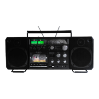
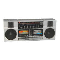
Specifies the physical size of the cassette recorder.
Indicates the total weight of the unit, including batteries.
Procedure for detaching the back cover of the cassette recorder.
Steps to separate the main chassis from the outer cabinet.
Instructions for carefully removing internal circuit boards.
Explains the Automatic Music Select System (AMSS) and its purpose.
Details how to operate the AMSS feature for music selection.
Provides a technical overview of the AMSS circuit's behavior.
Lists necessary preparations before performing amplifier adjustments.
Procedure to adjust head azimuth for optimal playback.
Steps to calibrate the audio playback output levels.
Adjusting bias and frequency response for recording and playback.
Procedure to calibrate the tuning indicator meter.
Steps for adjusting the FM stereo multiplex signal.
Adjusting stereo channel separation for optimal audio quality.
Setting the correct position for the tuning dial pointer.
Diagram showing the physical layout of internal components.
Detailed steps for aligning the FM tuner section.
Detailed steps for aligning the AM tuner section.
Schematic overview of the signal path during recording.
Schematic overview of the signal path during playback.
Measuring the torque applied to the take-up reel during operation.
Measuring the tape tension on the supply reel.
Procedure to adjust tape tension via pinch-roller pressure.
Details the audio frequency amplifier stage within the Dolby IC.
Describes the circuit that detects and manages overload conditions.
| Brand | Sanyo |
|---|---|
| Model | M9998 |
| Radio | Yes |
| Weight | 7.5 kg |
| Power Source | AC/DC |
| Speakers | 2 |
| Tuning Range | FM |
| Batteries | 8 x D batteries |