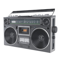
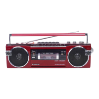
The Sanyo M9994K is a portable stereo cassette recorder, designed for both recording and playback, and features an integrated radio tuner with multiple bands. This device offers a comprehensive audio experience, combining the versatility of a cassette player with the functionality of a multi-band radio, making it suitable for various listening and recording needs.
Function Description:
The M9994K operates as a stereo cassette recorder, utilizing AC bias and a 4-track stereo system for high-quality audio recording. It employs AC erase for efficient tape clearing. The tape speed is standardized at 1-7/8 inches per second (4.75 cm/s). For radio reception, it includes an FM/AM/SW1/SW2 tuner, allowing users to tune into a wide range of broadcasts. The device supports various input and output terminals, including external microphone, phono, line in, line out, external speaker, and headphones, providing flexibility for connecting to other audio equipment. An auto-stop mechanism is integrated to protect the tape and the device by automatically stopping operation at the end of the tape in REC or PLAY modes. This mechanism is designed to prevent tape damage and reduce wear on the motor. When the PAUSE button is locked, the auto-stop mechanism is disengaged, allowing for continuous operation without interruption.
Important Technical Specifications:
- Recording System: AC bias, 4 tracks stereo
- Erasing System: AC erase
- Tape Speed: 1-7/8 i.p.s. (4.75 cm/s)
- Rewind Time (C-60): 2 minutes
- Fast Forward Time (C-60): 2 minutes 20 seconds
- Frequency Range:
- FM: 87.5 - 108 MHz
- AM: 530 - 1605 kHz
- SW1: 2.3 - 7.0 MHz
- SW2: 7.0 - 22 MHz
- Terminal Impedance:
- EXT. MIC: 5k ohms (0.3mV)
- PHONO: 50k ohms (3mV)
- LINE IN: 180k ohms (60mV)
- LINE OUT: 1k ohms (0.7V)
- EXT SP: 2.5 - 8 ohms
- HEADPHONES: 8 ohms
- Frequency Response:
- CrO2: 50 - 15,000Hz
- FeCr: 50 - 15,000Hz
- NORMAL: 50 - 14,000Hz
- Output Power: 7W x 2 maximum
- Power Source:
- DC: 12V "D" (UM-1) x 8 batteries, 12V Car battery
- AC: 120/200/240V 50/60Hz
- Dimensions (W x D x H): 20-3/8" x 5-1/4" x 12-1/16" (516 x 131 x 306 mm)
- Weight: Approximately 16 lbs. 12 ozs. (7.6 kg) including batteries.
Usage Features:
The M9994K is designed for user convenience with clearly labeled controls for volume, input volume, tone (bass and treble), and tuning. The device's multi-band radio allows for versatile listening options, from local FM stations to international shortwave broadcasts. The inclusion of various input terminals enables users to connect external microphones for recording, phono players for playback, or other audio devices via line-in. The line-out and external speaker terminals offer options for connecting to external amplification systems or larger speakers, enhancing the audio experience. The headphone jack provides a private listening option. The auto-stop mechanism ensures that the tape and motor are protected from unnecessary wear at the end of a cassette.
Maintenance Features:
The service manual provides detailed instructions for several adjustments to ensure optimal performance of the M9994K. These include:
- Torque Adjustment: This involves measuring and adjusting the torque for PLAY, FAST FORWARD, and REWIND modes to specified ranges (35-60 g/cm for PLAY, 60-100 g/cm for FAST FORWARD, and 65-100 g/cm for REWIND). If the torque is out of specification, cleaning the drive belt, flywheel, motor pulley, take-up reel, idler, and rewind roller with alcohol is recommended.
- Pinch Roller Adjustment: The contact pressure of the pinch roller should be measured with a tension gauge and adjusted to a range of 300-400 gr. Adjustments can be made by bending or replacing the spring.
- Tape Speed Adjustment: To ensure accurate playback speed, a frequency counter is connected to the external speaker jack, and a 3 kHz test tape is played. The potentiometer inside the motor is then adjusted until the counter reads between 2970-3020Hz.
- Head Azimuth Adjustment: For optimal tape reproduction, a music tape is played, and a screwdriver is used to turn the azimuth adjusting screw until the maximum sound is achieved.
- Adjustment of Stand-by Mechanism: The resultant force of the lock-lever system should be 100g or smaller. If it exceeds this, the spring coil 331 should be adjusted or replaced.
- Adjustment of Amplifier Section: This includes setting the unit to DC12V, turning tone controls to center, and input volume controls to maximum.
- Recording Gain Adjustment: With a blank tape inserted and a 1kHz-25dB (55mV) signal applied to the LINE IN jacks, SVR702 is adjusted until left and right channel outputs are identical.
- Playback Gain Adjustment: Using a 1kHz, 0dB playback test tape, SVR701 (50KB) is adjusted to equalize outputs at LINE OUTs for both channels.
- Meter Adjustment: With a 1kHz, 0dB playback test tape and the volume control set for a 2W (0VU) reading on the right channel, SVR703 is adjusted until both meters read identically.
- ALC Adjustment: After recording gain adjustment, a 1kHz-5dB (1.7V) signal is applied to the LINE IN jacks, and SVR70 is adjusted for identical outputs from both channels.
- Bias Adjustment: With a blank tape in recording mode, a VTVM is connected to the 10-ohm terminals of R845 and R945, and SVR801 and SVR901 are adjusted until the VTVM reads 3.5mV.
- Adjustment of Tuner Section:
- Tuning Meter Adjustment: A 98MHz, 80dB (10mV) signal is supplied to TP1 and TP2, and SVR301 is adjusted until the meter needle points to 9.5.
- FM Multiplex Adjustment: This involves setting SVR501 (10KB) to its center, modulating the FM signal generator with specific pilot and stereo signals, adjusting SVR501 for 19kHz ± 100Hz at TP3, and performing separation adjustments for both left and right channels by minimizing signal leakage using SVR502 (500B).
- MW, SW1, and SW2 Adjustments: These sections detail specific adjustments for each radio band, involving connecting signal generators, VTVMs, and oscilloscopes to various test points and adjusting coils and trimmers to achieve optimal reception and sensitivity at different frequencies across the dial scale. These adjustments typically involve setting the dial pointer to the extreme left, using a plastic-grip screwdriver, and ensuring the AFC switch is off for FM adjustments.
The detailed disassembly instructions for the cabinet and chassis, along with the stringing procedure for the dial rope, facilitate repair and maintenance. The parts list, including modification notices for specific ICs and associated components, ensures that correct replacement parts are used, especially for models with updated components.