Do you have a question about the Sanyo M7770K and is the answer not in the manual?
Procedure for removing the bottom cabinet cover.
Steps to detach the main radio chassis from the unit.
Instructions for removing the amplifier printed circuit board.
Steps for detaching the radio tuner printed circuit board.
Guide to removing the tape mechanism chassis.
How to remove the cassette compartment lid.
Important considerations for reassembling the unit.
Adjusting the solenoid for the Automatic Music Select System.
Calibrating the tape playback speed accurately.
Aligning the playback/record head for optimal sound.
Alignment procedure for the Medium Wave band.
Alignment procedure for Shortwave band 1.
Alignment procedure for Shortwave band 2.
Alignment procedure for the Frequency Modulation band.
Adjusting the FM stereo multiplex signal.
Adjusting the 38kHz oscillator circuit.
| Type | Cassette Player |
|---|---|
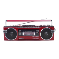
| Brand | Sanyo |
| Model | M7770K |
| Speakers | Built-in |
| Output Power | 2.5W |
| Power Source | AC |
| Frequency Range | FM: 88 - 108 MHz |