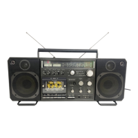
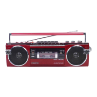
This document describes the Sanyo M9998LU Cassette Recorder, a portable stereo cassette recorder with integrated radio functionality.
Function Description
The Sanyo M9998LU is designed for recording and playback of audio on cassette tapes, as well as receiving radio broadcasts across multiple bands. It features a 4-track stereo recording system with AC bias and a 2-track AC erase system. The device incorporates an Automatic Music Select System (AMSS) to facilitate navigation and playback of recorded music.
The AMSS allows users to:
- Skip to the next tune: In playback mode, pressing the AMSS button followed by the FF-Cue/AMSS button will fast-forward the tape. Once the end of the current tune is detected, the FF-Cue/AMSS button automatically resets, and playback of the next tune begins after passing through any unrecorded segments.
- Repeat the current tune: In playback mode, pressing the AMSS button followed by the REW-Review/AMSS button will rewind the tape. Upon reaching the start of the current tune, the REW-Review/AMSS button automatically resets, and the same tune is repeated immediately.
- Skip multiple tunes: By repeatedly using the "skip to next tune" function, users can search for a desired tune by skipping several preceding tracks.
The AMSS operates by detecting playback signals from the head. When an unrecorded (no-signal) segment is found, a single-shot pulse is generated to activate the plunger, which controls the tape transport mechanism. The system includes astable multivibrator circuits (Q703, Q704) that oscillate when power is supplied (e.g., by closing S623 or S633 via the FF-Cue/AMSS or REW-Review/AMSS buttons), causing LEDs (D705 or D706) to flicker, indicating the tape's running direction. Diodes D707 and D708 are included to prevent over-current.
Audio sources (playback signals) from the right and left heads are fed into tape equalizer and Dolby amplifiers. Transistor Q712 amplifies audio sources in the AF (audio frequency) amplifier. A low-cut filter, composed of capacitor C731 and resistor R730, eliminates low-frequency components. IC703 integrates AM amplifier, AC-DC converter, and comparator circuits to amplify audio, detect levels, and generate pulses. Transistor Q706 generates single-shot pulses in its collector, with timing set by capacitor C718 and resistor R733. Transistor Q713 prevents erroneous actions in the muting circuit. Transistors Q707 and Q708, linked by a Darlington connection, use small-current single-shot pulses to drive the plunger. When the plunger moves, it pulls the slide (123) of the mechanism, resetting the locked FF-Cue/AMSS or REW-Review/AMSS button. Diode D709 prevents counter-electromotive current during plunger movement.
Important Technical Specifications
- Recording System: AC bias, 4-track stereo
- Erasing System: AC erase, 2-track
- Tape Speed: 4.75 cm/sec (1-7/8 i.p.s.)
- Rewind Time (C-60): 1 min. 35 sec.
- Fast Forward Time (C-60): 1 min. 50 sec.
- Frequency Range:
- FM: 87.5 - 108MHz
- SW: 5.95 - 18MHz
- MW: 525 - 1,605KHz
- LW: 150 - 285KHz
- Terminal Impedance:
- MIC: 10 kohms (0.3mV)
- PHONO: 50 kohms (3mV)
- REC/PB: (input) 10 kohms (1mV), (output) 2.7 kohms (0.5V)
- EXT SP: 4 - 8 ohms
- PHONES: 8 ohms
- Frequency Response:
- NORMAL: 40 - 12,000Hz
- CrO2: 40 - 15,000Hz
- METAL: 40 - 16,000Hz
- Signal to Noise Ratio:
- Dolby NR ON: 59 dB
- Dolby NR OFF: 50 dB
- Output Power: 12W x 2 maximum (music power)
- Power Source:
- DC: 15V "D" (UM-1) x 10 batteries
- 12-15V Car battery adaptor
- AC: 115/230V, 50/60Hz
- Dimensions (W x D x H): 664 x 175 x 267 mm (26-3/16" x 6-15/16" x 10-9/16")
- Weight: Approx. 9 kg (19 lbs. 14 ozs.) including batteries
Usage Features
The device is designed for ease of use with clearly labeled controls. The AMSS system provides convenient tape navigation, allowing users to quickly find and repeat songs. The multi-band radio tuner offers a wide range of reception. The inclusion of MIC and PHONO inputs allows for external audio sources to be recorded, while REC/PB terminals provide flexibility for connecting to other audio equipment. The EXT SP and PHONES outputs offer various listening options.
Maintenance Features
The manual provides detailed instructions for dismounting the cabinet and chassis, which is essential for servicing and repairs.
Dismounting the Cabinet and Chassis:
- Removing the back lid: First, remove batteries and disconnect the power cord. Unscrew eight pan head tapping screws (3 x 40 mm), including two in the battery case. Carefully open the back lid, disconnecting lead sockets from the set's PCBs to the back lid's PCBs. The manual lists the specific PCB connections (e.g., Beat cancel to Oscillation PCB, Speaker selection to Front socket PCB, etc.).
- Removing the cabinet: Remove all control knobs and levers. The power button and battery check/dial light button should be turned clockwise and counterclockwise to lock them in raised positions. Unscrew four red screws (3 x 30 mm, 1 x 40 mm) joining the chassis to the cabinet. Separate the microphone socket from the amplifier PCB and remove screw 209 (3 x 8 mm) from the oscillation PCB (110). Disconnect the three sockets of the LED PCB (106) from the AMSS PCB (107). The chassis can then be carefully lifted and separated from the cabinet.
Removing Printed Circuit Boards (AMP PCB and Tuner/Switch PCB):
- Amplifier PCB: Remove five screws (pan head tapping screw w/washer 3 x 12 mm) and two lugs (136 and 138) from the chassis. The AMP PCB connects to the tuner/switch PCB via plugs and can be separated by pulling it forward. When re-mounting, ensure the AMP side plug fits well with the tuner side socket.
- Switch/Tuner PCB: After removing the AMP PCB, remove three screws (one pan head tapping screw w/washer 3 x 8 mm, two pan head tapping screws 3 x 8 mm) from the tuner/switch PCB. Remove the hexagon head bolt (2.6 x 16 mm) from the dial drum (66) and separate the spring coil (67) for rope threading from the drum. Glue the spring coil with adhesive cellophane tape and pull it outward to loosen the PCB. Carefully pull the PCB along the chassis groove to avoid damaging leads. When dismounting, be careful not to separate the connection bandy cord from the amplifier PCB. When reassembling the chassis into the cabinet, arrange the leads from the VR PCB as illustrated to prevent pinching or cutting.
Adjustments:
- Amplifier Adjustments:
- Head Azimuth: Load a 10 kHz, -10 dB test tape and press PLAY. Adjust the head azimuth screw until the LINE OUT level is maximum. Repeat for both channels and both sides of the tape.
- Playback Level: Play a Dolby test tape (MTT-115 0dB, TEAC Dolby level calibration tone 200 nWb/m). Adjust controls SVR801 (L-ch) and SVR901 (R-ch) until the output level at the measuring test point (common terminals of record/playback switch S806 and S906 on point 7 of Dolby IC (LM1011N Dolby), IC801, IC901, and ground) reaches 0.58 V.
- Record/Playback Frequency Response (Bias Adjustment): Feed a 5 mV (-46 dB) 1 kHz input signal into the line input terminal. Turn the input control knob until the output at measuring test points is 40 mV. Adjust SVR701 and SVR702 until the difference between record output and playback output is 0 for both 1 kHz and 10 kHz signals. Set the line input signal to "OFF" during adjustment.
- ALC Balance: Turn on the ALC switch. Feed a 500 mV (-6 dB) input signal into the line input terminal. Set to record mode. Adjust SVR703 until levels at measuring test points are uniform.
- Tuning Meter: Feed a 98 MHz, 66 dB input signal into the set. Tune to the reception frequency and adjust SVR301 (10 kB) until the meter swings up to graduation 9.5. If the meter swing increases with input, adjust after raising the input until the meter stabilizes. If the maximum meter swing doesn't coincide with the maximum output point, turn off the AFC switch (short-circuit TP4 and shield case) and tune to the maximum output point. Adjust T303 for maximum output with 50 dB input.
- Record and Playback Levels: Feed a 50 mV (-26 dB) 1 kHz input signal into the line input terminal. Turn the input control knob until the output at measuring test points is 0.58 V. Record, then adjust SVR802 and SVR902 so that the record input equals the playback output. Set the line input signal to "OFF" during playback.
- FM MPX (Multiplex) Adjustment:
- Set SVR501 (10 kB) to the central position.
- Apply modulation input into FM SG through a stereo modulator (400 Hz modulation frequency, 7.5 kHz pilot signal deviation, 22.5 kHz stereo signal deviation).
- With the stereo modulator output signal switch at MAIN (L + R), set the radio's reception frequency to 98 MHz and tune with FM SG (66 dB output).
- 19 kHz Adjustment (V.C.O. adjustment): In FM stereo mode, connect a frequency counter to TP6, and cut the stereo modulator output to no-modulation state (turn off PILOT and MAIN & SUB of output signal switch). Adjust SVR501 (10 kB) to 19 kHz ± 50 Hz.
- Separation Adjustment:
- Turn tone controls to minimum and set the balance control to the middle.
- Turn on MAIN & SUB signal switch and PILOT signal switch, and set the output signal switch to "MAIN" position.
- Connect a VTVM to external speaker terminals (right and left jacks).
- Turn volume controls to adjust output of both channels to 50 mW.
- Turn on the RIGHT side and turn off the LEFT side of output signal switch. Adjust SVR502 (1 kB) to minimize the LEFT side leakage output.
- Turn on the LEFT side and turn off the RIGHT side of output signal switch. Adjust SVR502 to minimize the RIGHT side leakage output. If the adjustment position coincides with step 5, adjustment is complete.
- If the adjustment position differs, adjust so that separation of both channels is nearly equal. Separation should be >20 dB at 400 Hz, 1 kHz, and >10 dB at 10 kHz.
- Threading of Dial Rope: Tie the rope to the spring coil (67) of the drum (66) with a folded length of 512 mm. Mount the spring coil with rope on the drum and thread the rope in the direction of arrows (numerical sequence). Wind four turns on the tuning shaft, then return to the spring coil of the drum.
- Pointer Position Adjustment: Rotate the tuning shaft counterclockwise until it turns idle. Fit the pointer to the left end point and secure it firmly.
Mechanism Adjustments:
- Take-Up Torque: Set the unit to PLAY, F.FWD, or REW mode. Measure torque with a torque gauge.
- PLAY: 35-60 g/cm
- FAST FORWARD: 70-130 g/cm
- REWIND: 70-130 g/cm
If torque is below standard, clean the drive belt, flywheel, motor pulley, take-up reel idler, and rewind roller with alcohol-soaked cotton swab.
- Back Tension: Make a hole in the side of the cassette (as shown in figure two). Measure back tension with a tension gauge, ensuring the tape does not rub against the cassette edge.
- PLAY: Less than 5 g/cm
- FAST FORWARD: Less than 5 g/cm
- REWIND: Less than 5 g/cm
- Tape Tension: Cut a length of tape. Tie one end to a thread connected to a tension gauge, leaving the other end hanging loose. Operate the unit in PLAY mode and hold the tension gauge steady. If the reading is over 120 grams, no adjustment is needed. If it is under 120 grams, adjust the pinch-roller pressure by bending the spring wire 32 (141-2-852T-55700) as shown in the exploded view. Clean the pinch roller with alcohol to prevent tape slip.