“.
CD PLAYER ADJUSTMENTS
b. PREPARATIONS
WA”
(a) Measuring instruments, tools and filter
(I j
(2)
(3)
(4)
Test disc. : YEDS 18 ( SONY ) or etc.
Oscilloscope : SS5711
(1O MHz or dual-phenomenon )
or Memory scope : DSS6521 (Storagescope)
DC digital voltmeter (Input impedance
1M ohm or more )
AC voltmeter (- 80 dB, input impedance
(5) AF oscillator (400 Hz, 300 mV RMS )
(6) Frequency counter (5 MHz ; or more )
and probe (10 : 1)
(7) Screwdrivers ( non-metallic ) for adjustments
(8) Low Pass Filter ( L.P.F. )
(9) DC Power supply :12 V, 1 A
1 M ohm or more)
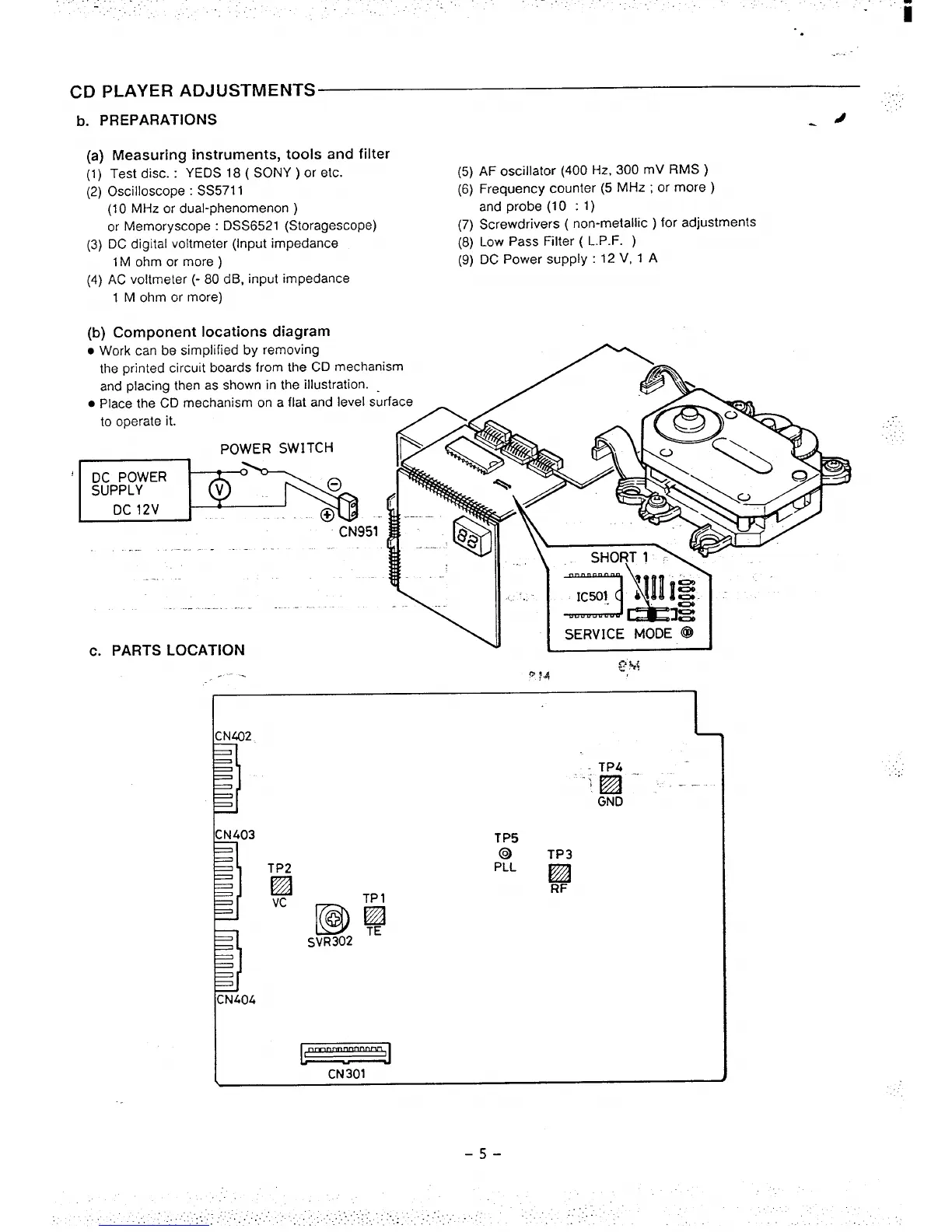
(b) Component locations diagram
● Work can be simplified by removing
the printed circuit boards from the CD mechan
and placing then as shown in the illustration.
. Place the CD mechanism on a flat and level su
to operate it.
POWER SWITCH
‘~
CN951-
. .
-.
.
c. PARTS LOCATION
Q~+
.-..
P f.d
I
II
CN403
P
CN404
L
TP4
-M ‘“ :__..
GND
TP2
❑
Vc
TP5
2’ ‘;
RF
TP 1
@lz#
SVR302
(
—
CN301
..
-5-
 Loading...