.
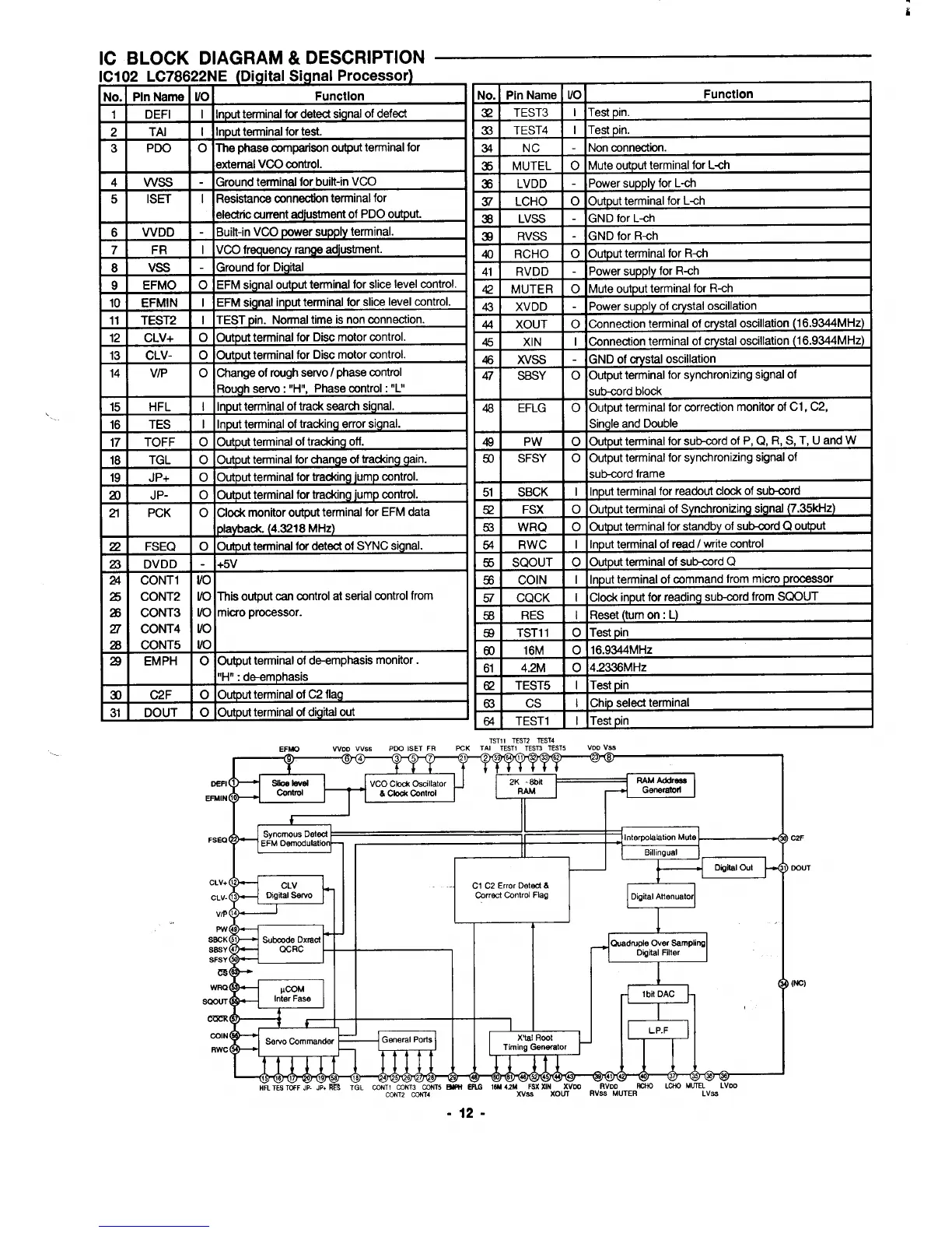
IC BLOCK DIAGRAM& DESCRIPTION —
IC102 LC78622NE (Digital Signal Processor)
No. I Pin Name] VOI Function
I
1
DEFI
I Inputterminal fw deted signalof defect
2
TAI
I Inputterminal for test.
3
PDO
o Tha phase comparison outputterminal for
I
I I
Iextemal VCOcontrol.
I
41 Vvss I - lGround terminal for built-in VCO
51
IS13
1 IResistance connection terminal for
I
I I
electric current adjustment of PDO output.
61
VVDD - IBuik-in VCO power supply terminal.
7 FR I VCO frequency range adjustment.
8
Vss
-
Ground for Digital
9
EFMO
o EFM signal outpufterminal for slice level control.
10 EFMIN
I EFM signal inputterminal for slice level control.
11] TEST2
I
I ITEST pin. Normaltime is non
connection.
12 I CLV+ I O 10utpuf terminal for Disc motor control.
13 CLV- 0 Output terminal for Disc motor wntrol.
14 VIP
o Change of nnsghservo I phase control
Rough servo: “H”, Phase control: “L”
15 HFL I Inputterminal of track search signal.
16 ]
TES
I
I IInputterminal of tracking error signal.
17 I
TOFF
I O 10utput terminal oftracking off.
1181
TGL
I O ]Output terminal for change of tracking gain.
I
No. I Pin Name [ l/O I
Function
321 TEST3
I lTesf pin.
~sl
TEST4 I I
~361 LVDD I -
H
37 LCHO O
3 LVSS -
3a RVSS -
40 RCHO O
1411 RVDD I -
Tesf pin.
Non connection.
Mute output terminal for L*h
Power supply for L-ch
Output terminal for L-ch
GND for L-ch
GND for R-ch
Outpuf terminal for R-ch
~Powersupply for R-ch
42
MUTER
o Mute output terminal for R-ch
43 XVDD
- Power supply of crystal oscillation
44 XOUT o
Connection terminal of crystal oscillation (16.9344MHz)
45 XIN
I Connection terminal of crystal oscillation(16.9344MHz)
461 Xvss
I
- IGND of crystal oscillation
47 I SBSY I O ]Output terminal for synchronizingsignal of
I
I I
sub-cord block
481 EFLG
I O IOutput terminal for correction monitor of Cl,
C2,
Single and Double
49 Pw
o Output terminal for sub-cord of P, Q, R, S, T, U and W
50
SFSY
o Output terminal for synchronizing signal of
I
I I
sub-cord frame
I
19 JP+
o Output terminal fortrackingjump control.
ZO
JP-
0 Outp
ut terminal for tracking jump control.
51 [
SBCK
I
I IInputterminal for readouf clock of sub-cord
2f
PCK
o Clock monitor outputterminal for EFM data
521 FSX I O 10utput terminal of Synchronizing signal (7.35kHz)
playback. (4.3218 MHz)
Z?
FSEQ
o Outputterminal for detect of SYNC signal.
a DVDD
-
+5V
24
CONT1
I/o
z CONT2
I/o Thii outpuf can control at serial control from
25 CONT3
UO miao processor.
27
CONT4
I/o
B CONT5
I/o
29
EMPH
o Output terminal of de-emphasismonitor.
“H”: d~mphasis
3 C2F
o Output terminal of C2 flag
31 DOUT o Outputterminal of digitalout
~
O Ou ut terminal for standb of sub-cord Q o ut
I In ut terminal of reed /write control
I In ut terminal of command from micro rocessor
I Clock in ut for readin sub-cord from SQOUT
56 RES
I Reset (turn on: L)
93 TST11 o Test pin
60
16M o 16.9344MHz
61 4.2M o 4.2336 MHz
&
TEST5 I Test pin
~ 53
Cs
I Chip select terminal
M TEST1
I Test pin
=*
TST11 TEST2 TEST4
EFW
woo W&s
PDG ISET FR PCK TAI TEST1 TESTSTEST5
VDDv%
I
‘i’
VCO CM
Oscillator
RAM Address
h
Clod (2atml
I
i
I
@ted
,“,:. ”
Interpolslstion Mute
FSEO
correct control Flag
Oigital Attenuator
Ousdruple Over Sampling
SFSY
m
wm
SW4JT
CWrt
COIN
RWC
1
“., ,.! a! r “! L.
—
Ill- P-w-l
l’1~1~
@
16119521846 289
81 48
41
40
@
?a@J
HFl TESTOFF JP- JP+~ TGL CCN~&;NT;wT W ERG lW 42Mxv~SX SINXO;VW
RVDD W LC410 MUTEL
LVDD
RVSS MUTER
LVSS
32F
GOUT
[NC)
-12-
 Loading...