Do you have a question about the Sanyo MCD-ZX700F and is the answer not in the manual?
Details of the CD playback mechanism and performance.
General performance characteristics like output power and dimensions.
Radio reception frequencies and bands.
Cassette tape playback specifications.
Important safety warnings and guidelines for laser usage.
Procedures for adjusting the AM tuning and tracking.
Procedures for adjusting FM tuning and tracking.
Steps for replacing tape heads and initial precautions.
Procedure for aligning tape head azimuth for optimal playback.
Method for adjusting AC bias frequency for tape recording.
Steps to adjust motor speed for consistent tape playback.
Checking and measuring tape mechanism torques and tension.
Block diagram and pin description for the CD driver IC.
List of included accessories and packing materials.
Components related to the unit's physical structure.
Parts for the power supply printed wiring board.
Components for the display printed wiring board.
Fasteners and small hardware components.
Block diagram and pinout for the PLL IC.
Block diagram and function of the voltage regulator IC.
Block diagram and pin details for the digital signal processor.
Block diagram and pinout for the audio power amplifier IC.
Block diagram and pin description for the equalizer IC.
Block diagram and pinout for the servo signal processor IC.
| Brand | Sanyo |
|---|---|
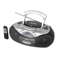
| Model | MCD-ZX700F |
| Mega Bass | Yes |
| Power Source | AC |
| Headphones | Yes |
| Speakers | 2 |
| Additional Features | Radio |