Do you have a question about the Sanyo SHP-C90GEN and is the answer not in the manual?
Conversion table for thermistor resistance and temperature for tank and heat pump sensors.
Winding resistance values for compressors at 25°C for different models.
Overview of the Sanyo CO2 ECO heat pump system and its key features.
Guidelines for initial checks before operation and essential safety precautions.
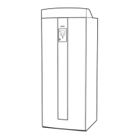
Description of the boiler's primary functions and identification of main components.
Details on the components and parts of the tank unit, including the display and controls.
Explanation of the display panel, status indicators, and control buttons (OK, Step, Reset).
Guidance on general handling and setting manual/maximum thermostats.
Operating the main screen, understanding standard settings, and navigating menus.
Instructions on how to access and navigate through the control system's menus.
Detailed explanation of the MAIN MENU display, including room and tank temperatures.
Explanation of the MENU CHOICE display and the LOGG MENU for long-term data.
Understanding how house temperature needs are set via curve inclination and adjustment.
Procedure for setting the curve inclination and adjustment for optimal heating.
Steps for basic adjustment and fine-tuning based on outdoor temperature.
Diagrams illustrating how curve inclination affects radiator temperature based on outdoor temperature.
Diagrams showing how curve adjustment shifts the heating curve.
Recommended basic settings for CURVE INCL and CURVE ADJUST based on system type.
How to program night temperature reductions for energy saving.
Guide to operating the control system, including main screen, menus, and step back functions.
General advice on maintenance checks after installation and basic upkeep.
Procedures for checking and manually operating the pressure release and mixing valves.
General advice on troubleshooting and checks for sanitary hot water errors.
Troubleshooting radiator system issues and procedures for resetting errors.
Understanding alarm texts and status messages displayed by the control system.
List and explanation of error codes (H01-H27) generated by the heat pump unit.
Understanding status messages and how the room sensor affects operation.
A table to record user-defined settings for various control parameters.
Schedule for setting different night temperatures throughout the week.
Detailed step-by-step instructions for removing the electrical box from the unit.
Graphs showing operating current versus outdoor temperature for SHP-C90GDN and SHP-C90GEN.
Table listing display codes, troubles, and diagnostic criteria for the tank unit.
List of heat pump unit error codes (H01-H11) with their corresponding troubles and diagnosis.
How errors are displayed on the initial and error screens.
Accessing and viewing the error history within the LOGG MENU.
Step-by-step procedures for resolving specific errors like H05, H23, H27, and COMM ERROR.
Key points to check during delivery and installation, plus safety instructions.
General installation regulations and details of pipe connections for the system.
Guidelines for operation, transport, delivery, basement heating, and domestic hot water safety.
Details on connecting the circulation pump, pressure relief valve, and expansion vessel.
Principle sketch showing system pipe connections with a numbered legend.
Instructions for filling the boiler and radiator system with water.
Procedure for releasing air and using the drain valve when connecting the heat pump.
Guidelines for electrical installation, including safety, supply, and main switch requirements.
Instructions for wiring the communication cable between the heat pump and boiler units.
Recommendations for optimal placement of the outdoor temperature sensor.
Overview of the terminal block for electric connections and cable fixings.
Wiring details for a 400V 3-phase, N supply system, including sensor and power connections.
Wiring details for a 230V 3-phase supply system, including sensor and power connections.
Instructions for installing room and primary flow sensors correctly.
Connecting radiator pump and performing checks on sensor connections and electrician adjustments.
Information and checks required before the first start-up, including water filling.
Steps for initial power-on, system start-up, and conducting the test run.
Post start-up checks to ensure system performance and user understanding.
Installer guidance and a summary of the installation procedure steps.
Key safety warnings, prohibited actions, and graphic symbol meanings.
Mandatory safety actions like grounding and prohibitions on unit modification.
List of parts packed with the unit and outline drawings showing dimensions.
Guidelines for choosing a suitable installation location, considering service and environmental factors.
Instructions for installing the heat pump unit outdoors on a stand, ensuring proper placement.
Diagram showing standard pipe connections between the tank and heat pump units.
Important checks and precautions for piping materials and installation.
Recommendations for piping materials and work practices to ensure proper connection.
Essential precautions for electrical work, including cable thickness and grounding.
Diagram and explanation of the lead-in wiring configuration from the distribution board.
Instructions and precautions for proper grounding of the tank and heat pump units.
Procedure for filling the tank unit with water and checking for leaks.
Instructions for insulating pipes to prevent heat loss and protect from weather.
Procedure for conducting a test run after preparation to ensure proper system function.
Checklist for verifying installation work, piping, and electrical connections.
Explanation of common symptoms like frost, fan cycling, and water leakage during operation.
Exploded view diagram illustrating the parts of the heat pump unit.
| Type | Electric Storage Water Heater |
|---|---|
| Capacity | 90 Liters |
| Voltage | 220-240V |
| Frequency | 50/60 Hz |
| Power Consumption | 2000 Watts |
| Heating Element | Copper |
| Thermostat | Adjustable |
| Safety Features | Pressure Relief Valve |
| Weight | 25 kg |