8
8-22. Common to All Models
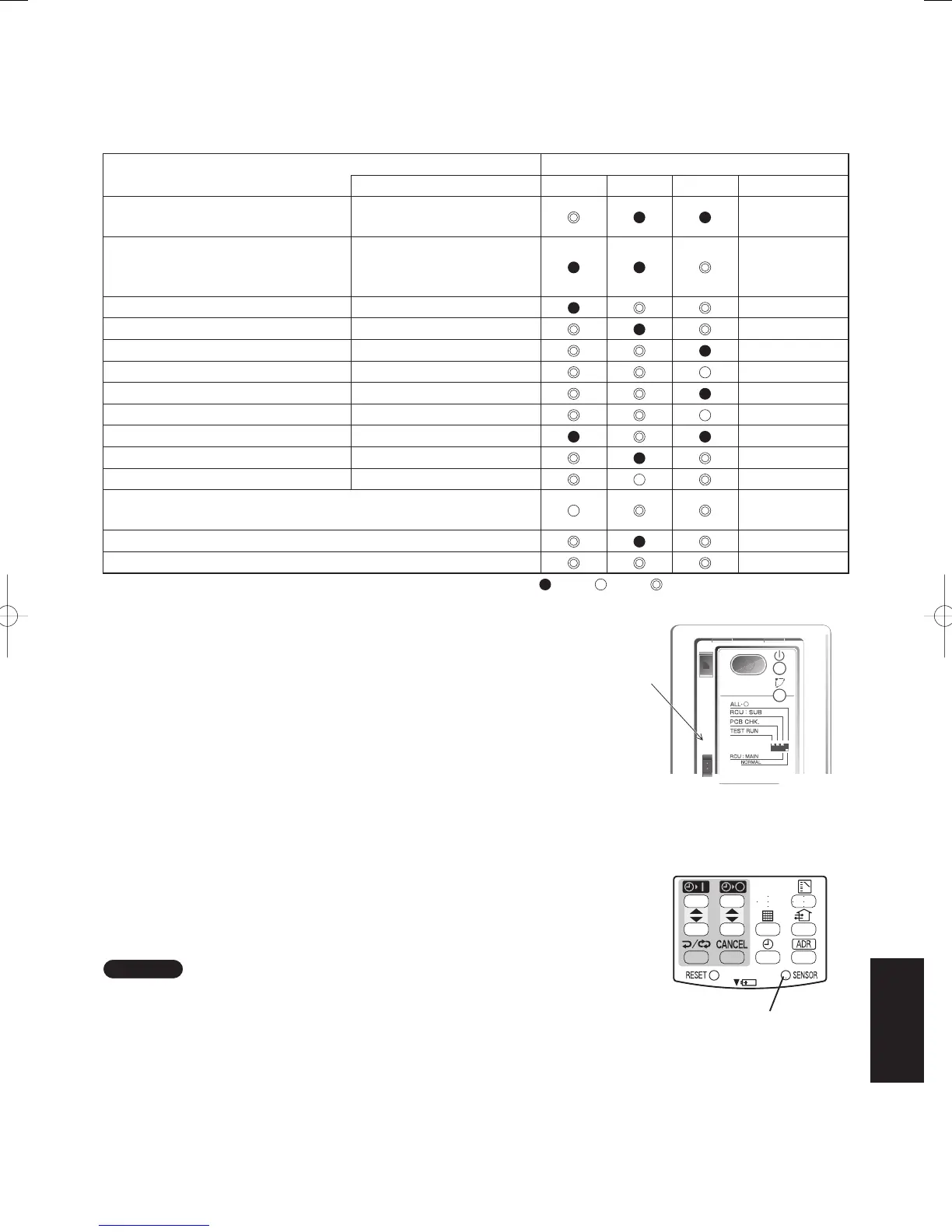
1. The Self-Diagnosis Function Display and What is Detected
Alarm Display in the table below indicates the content of alarms that are displayed when a wired remote control is
connected. For information on how to deal with the alarms, refer to the Mounting Instructions for the indoor unit or
to Test Run or servicing materials.
Error Detected WL Remote Control LED Display
Alarm Display Run Timer Standby Blinking
Communication error in the remote
control circuit
E01–E03, E08–E14, E17, E18
Communication error either in the in/
outdoor operation line or the sub-bus of
the outdoor unit
E04–E07, E15, E16, E19–E31
Operation of indoor protection device P01, P09–P14 Alternately
Operation of outdoor protection device P02–P08, P15–P31
Alternately
Error in the indoor thermistor F01–F03, F10–F11 Alternately
Error in the outdoor thermistor F04–F09, F12–F28
Alternately
Error in the indoor EEPROM F29
Simultaneously
Error in the outdoor EEPROM F30, F31
Simultaneously
Error related to the compressor H01–H31
Error in indoor settings L01–L03 L05–L09 Simultaneously
Error in outdoor settings L04, L10–L31
Simultaneously
Inconsistency in Air/Heat (Including an auto-temp setting for a model
without auto-temp settings)
Alternately
Oil Alarm (Same as operation of outdoor protection device)
Alternately
Test Run
Simultaneously
: Off / : On / : Blinking (0.5 sec. intervals)
When using RCS-BH80BG.WL
If you have either an outdoor maintenance remote control or a wired
remote control and a service checker special wiring (623 178 5082 :
for service use) at hand, you can get more detailed information about
an alarm by connecting one to the service connecter as in the diagram.
For information such as how to connect to receivers, etc., refer to the
Users Manual that came attached with the service checker special
wiring.
2. Room Temperature Sensor Settings
Common to All Models
• The indoor unit and the wireless remote control are equipped with
indoor temperature sensors. The sensing of indoor temperature
works via one of them.
• When the unit is shipped, it is set to the indoor unit, but to switch to
the remote control, press the Sensor button (diagram at right) inside
the remote control’s cover and then check to make sure that Main
Sensor on the LCD screen goes off.
NOTE
Even when the Sensor switch has been set to the remote control,
if the unit does not receive any room temperature data from the remote
control for ten minutes, it automatically switches back to the indoor unit
sensor, so be sure to install the remote control facing the receiver.
Service
Connector
Sensor Button
Fig. 8-36
Fig. 8-37
8-25
SM830160-03ClassicPAC-iA4.ind2525SM830160-03ClassicPAC-iA4.ind2525 2010/02/1610:31:232010/02/1610:31:23

 Loading...


