2
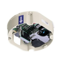
Name of parts
Install this power board unit securely according to your camera installation manual.
Be aware that allowing the unit to fall may cause personal injury.
This installation should be made by a qualified service person and should conform to all
local codes.
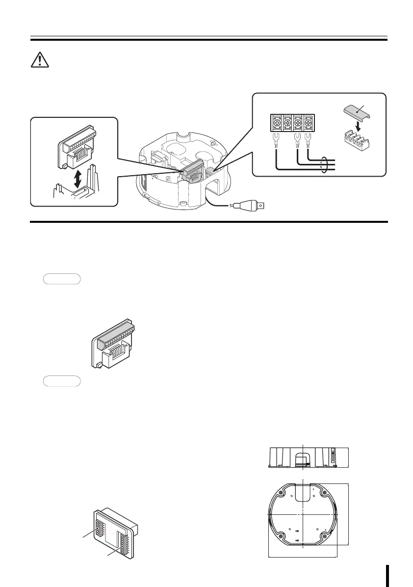
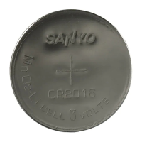
1 Joint board
The joint board can be removed by pulling it
up. When connections and settings are done,
push it down until you hear a click.
• Camera control (RS485A/B)
• Alarm signal input (IN1 - 8)
• Alarm signal output (OUT1/2)
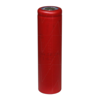
1System control setting switches
• Baud rate setting (BAUD RATE 0/1):
2400/4800/9600/19200
• Control method setting (485/COAX)
• Protocol setting (SSP/PELCO)
• Terminate setting (TERMINATE)
2Address setting switches (ADR)
SANYO protocol: 1 - 127
PELCO protocol: 1 - 255
• When setting the address by using the
menu screen on the camera, set the
address setting switches to “0”.
2 Power input terminals
For connection to the terminals L and N, use
AWG18 or higher cables. Use solderless
terminals (ring or spade type) for wiring. After
connection, always install the supplied power
terminal cover A.
L: Live
N: Neutral
G: Ground
3 Video output connector (BNC)
Connect the video cable from the monitor.
b Specifications
Power supply:
AC 24 V ±10 %, 50/60 Hz
Power consumption: 16 W
Weight: Approx. 480 g (1.1 lbs.)
3
1
2
A
GNL
To AC 24 V
SIDE-A
SIDE-B
1
186 (7.3)
166 (6.5)
54 (2.1)
Dimensions: mm (inch)
L9EBD_WA(VA-84S).book 2 ページ 2007年2月1日 木曜日 午前10時5分