Adjusting / Checking method:
1. Adjust with VR1OI to 0.5 t 0.01 VP-P,
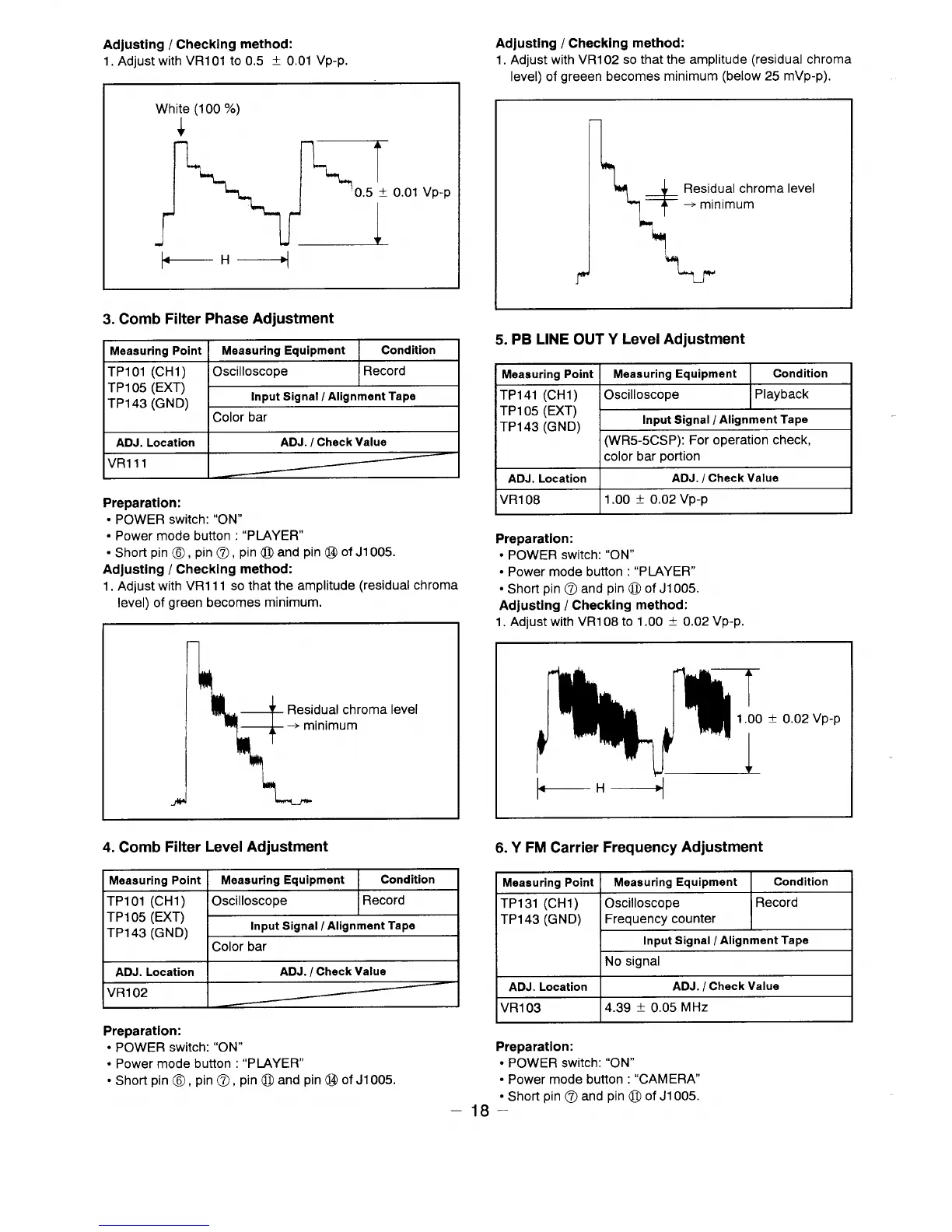
Adjusting / Checking method:
1. Adjust with VR102 so that the amplitude (residual chroma
level) of greeen becomes minimum (below 25 mVp-p).
White (100 %)
1
+“+
Residual chroma level
+ minimum
0.01 Vp-p
I
)
3. Comb Filter Phase Adjustment
5. PB LINE OUT Y Level Adjustment
Measuring point I
Measuring Equipment
I
Condition
I
I Measuring Point I
Measuring Equipment
Condition
TP101 (CH1)
I Oscilloscope
I Record I
TP105 (EXTj
TP143 (GND)
~
TP141 (CH1)
TP105 (EXT)
TP143 (GND)
-
(WR5-5CSP): For operation check,
ADJ. Location
ADJ. / Check Value
VR111
I ] color bar Dortion
ADJ. Location
ADJ. / Check Value
VR108
1.00 k 0.02 Vp-p
Preparation:
● POWER switch: “ON”
● Power mode button : “PIAYER”
● Short pin @, pin @, pin @ and pin @ of J1OO5.
Adjusting / Checking method:
1. Adjust with VR111 so that the amplitude (residual chroma
Preparation:
● POWER switch: “ON”
● Power mode button : “PLAYER”
● Short pin @ and pin @ of J1oO5.
Adjusting / Checking method:
1. Adjust with VR108 to 1.00 f 0.02 Vp-p.
level) of green becomes minimum.
\
+
Residual chroma level
+ minimum
I
-Id
1
4. Comb Filter Level Adjustment
6. Y FM Carrier Frequency Adjustment
Measuring point I
Measuring Equipment
I
Condition
Measuring Point
Measuring Equipment
Condition
TP131 (CH1)
Oscilloscope
Record
TP143 (GND)
Frequency counter
Input Signal / Alignment Tape
No signal
TP101 (CH1)
IOscilloscope
I Record I
TP105 (EXTj
TP143 (GND)
~
ADJ. Location
ADJ. / Check Value
VR102
ADJ. Location I
ADJ. / Check Value
VR103
4.39 t 0.05 MHz
Preparation:
● POWER switch: “ON”
● Power mode button : “CAMERA
● Short pin @ and pin @ of J1OO5.
18 –
Preparation:
● POWER switch: “ON”
● Power mode button : “PLAYER”
● Short pin @, pin @, pin @ and pin @ of J1OO5.
 Loading...