2-9. AUDIO CIRCUIT (For VM-EX450P/480P/550P/560P)
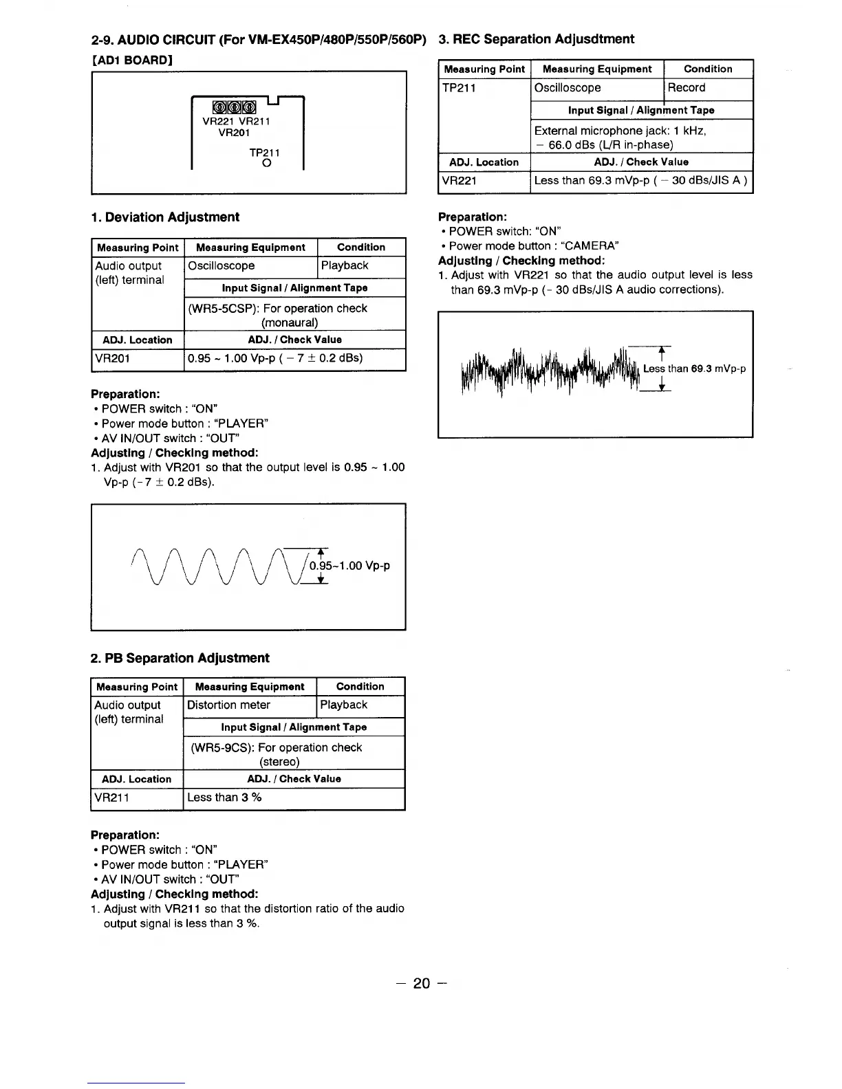
[AD1 BOARD]
rl
Kmm2
VR221 VR211
VR201
TP211
o
1. Deviation Adjustment
Meaauring Point Meaeuring Equipment
Condition
Audio output Oscilloscope
Playback
(left) terminal
Input Signal / Alignment Tape
(WR5-5CSP): For operation check
(monaural)
ADJ. Location
ADJ. I Check Value
VR201 0.95-1.00 VP-P ( – 7 f 0.2 dBs)
Preparation:
● POWER switch : “ON”
● Power mode button : “PLAYER”
● AV iN/OUT switch : “OUT
Adjusting / Checking method:
1. Adjust with VR201 so that the output level is 0.95-1.00
Vp-p (-7 t 0.2 dBs).
‘V’vvml-’”oovp-p
2. PB Separation Adjustment
I Meaauring Point I Meaauring Equipment I Condition I
Audio output
(left) terminal
I Distortion meter
I Playback I
Input Signal / Alignment Tape
(WR5-9CS): For operation check
(stereo)
ADJ. Location
ADJ. / Check Value
VR211 Less than 3
Y.
3. REC Separation Adjustment
Meaauring Point I
Measuring Equipment Condition
TP211 I Oscilloscope
I Record I
Input Signal / Alignkent Tape
External microphone jack: 1 kHz,
– 66.0 dBs O_/Rin-~hase)
ADJ. Location
ADJ. I Check Value
VR221
Less than 69.3 mVp-p ( – 30 dBs/JIS A )
Preparation:
● POWER switch: “ON”
● Power mode button : ‘{CAMERA
Adjusting / Checking method:
1. Adjust with VR221 so that the audio output level is less
than 69.3 mVp-p (- 30 dBs/JIS A audio corrections)
han 69.3 mVp-p
Preparation:
● POWER switch : “ON”
● Power mode button : “PIAYER”
● AV lN/OUT switch : “OUT”
Adjusting / Checking method:
1.
Adjust with VR211 so that the distortion ratio of the audio
output signal is less than 3
‘%0.
–20–
 Loading...