Do you have a question about the Sargent 1431 series and is the answer not in the manual?
Instructions for mounting the closer on the hinge side of the door.
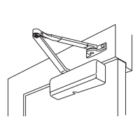
Instructions for mounting the closer on the stop side of the door using the PH9 arm.
Instructions for mounting the closer on the frame's stop side.
Choose closer position based on maximum door opening.
Prepare door and frame with pilot holes for screws.
Mount closer body to door and install main arm on spindle.
Secure hold open foot to frame with correct nut orientation.
Details on optional accessories like cover plates and mortise feet.
Choose closer position based on maximum door opening.
Prepare door and frame with pilot holes for screws.
Mount closer body to door and install bracket onto frame.
Mount main arm on spindle and connect rod to swivel arm.
Secure hold open foot to frame with correct nut orientation.
Choose mounting position based on reveal depth.
Locate and mark holes, then install closer body and rod assembly.
Mount main arm on spindle and connect rod to swivel arm.
Secure hold open foot to frame with correct nut orientation.
Adjust closing, latching, backcheck, and delayed action speeds.
Modify the tension of the hold open arm.
Instructions for installing the closer cover.
| Type | Electromagnetic Lock |
|---|---|
| Mounting | Surface Mount |
| Lock Type | Electromagnetic |
| Compliance | UL Listed |
| Voltage | 12/24 VDC Field Selectable |
| Current Draw | 12VDC: 250mA continuous; 24VDC: 125mA continuous |
| Holding Force | 1200 lbs |
| Operating Temperature | -15° to 150° F (-26° to 66° C) |
| Compatibility | Compatible with access control systems |