12
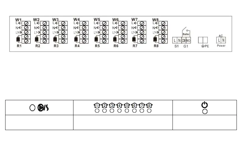
Connectors and wiring
L –
Live N – Neutral PE – Grounding, Earth
W1 do W8 –
Heating zones
R1 do R8 – Connectors for each thermal actuators or heating zones
S1 – Connector for manifold pump
G1 – Volt free contact for connecting a heating source or a boiler, etc…
Front side LED indicators
For easier use and understanding, the device has an LED indicator on the front side. The description of the indicators
is described below.
When the heat source or the
manifold pump is activated, this
LED indicator turns on (red)*.
When there is a need for heating, the indicator
under the particular number (1-8) turns on
If the device is turned on or
plugged in to power supply,
the LED indicator turns red.
* If there is no output on the exit 1-8 and are turned off, the next output of the heating source, pump, starts with a delay
of 3-5 minutes.
 Loading...