DS 3.401 4 - 10 11/99
OPERATION
WHEN ACTUATOR IS OPERATING BEWARE OF TRAPPING
FINGERS ETC.
The stroke of the 'AL' Linear Actuator is self-setting, using load-
dependent switches, and is determined by the stroke of the valve. The
ALE requires only a simple adjustment. Consequently, all
specifications of actuator are universal and can be fitted to any seat
valve having a stroke length within its nominal range, see details under
'Specifications' on page 2 and 'Valve Stroke Time' on page 3.
The drive can be disconnected for manual operation. A button located
on the top surface of the enclosure is connected to a spring loaded
push rod assembly. When depressed this moves the 2nd gear out of
mesh, this mechanism can be locked in place by moulded ledges in the
housing. Adjacent to this is a manual operation key, which is clipped in
place on the top surface of the enclosure. The key can be fitted into a
slotted feature in the end of the main drive shaft, which protrudes
through the top surface of the enclosure. With the drive shaft
disconnected from the gearbox/motor the manual operation key can be
used to provide manual operation of the actuator.
ALM and ALX Actuators
The load-dependent switches perform a combined limit and transfer
function. The limit switches de-energise the actuator at the end of
stroke, whilst the transfer switches are used basically for sequence
operation in multi-stage applications. Where additional switching or
interlocking functions are required, use the add-on auxiliary switch
accessory or built-in auxiliary switch detailed under 'Specifications'.
When energised between terminals 1 and 3, the actuator moves its
spindle towards the fully extended position, to open a Satchwell 2-port
or 3-port valve to the heat exchanger.
Conversely, when energised between terminals 2 and 3, the actuator
moves its spindle towards the fully retracted position, to close the
valve.
The load-dependent limit switches transfer the control signal from
terminal 1 to 1T and from terminal 2 to 2T at the respective limits of
valve stroke.
ALE Actuators
The ALE incorporates an electronic positioner and provides
modulating control from any controller having a 0-10Vdc output. Using
the 'START' and 'SPAN' adjustments, the actuator can be set to make
a complete stroke over any span from 4 to 10 volts, starting at any point
within the signal range, providing the sum of 'START' Volts plus 'SPAN'
Volts does not exceed 10. The load-dependent limit switches operate
basically as described for the ALM and ALX, but are internally
connected between the electronics card and the motor windings.
Where additional switching or interlocking functions are required, use
the add-on auxiliary switch accessory or built-in auxiliary switch
detailed under 'Specifications'.
A separate 0-10Vdc output is available (terminal 11) for indicating
actuator position to a Building Management System or as a Service
and Commissioning aid.
ALE actuators can be set to operate a low hysteresis when used for
tight control applications on microprocessor based controllers. The
hysterisis is set by using a jumper link on the actuator PCB (see the
commissioning section for details). A low hysterisis setting gives 200
steps between 0 and 10Vdc input and the standard setting gives 25
steps.
The following adjustments are made on the electronic printed circuit
board, accessible behind the removable front cover.
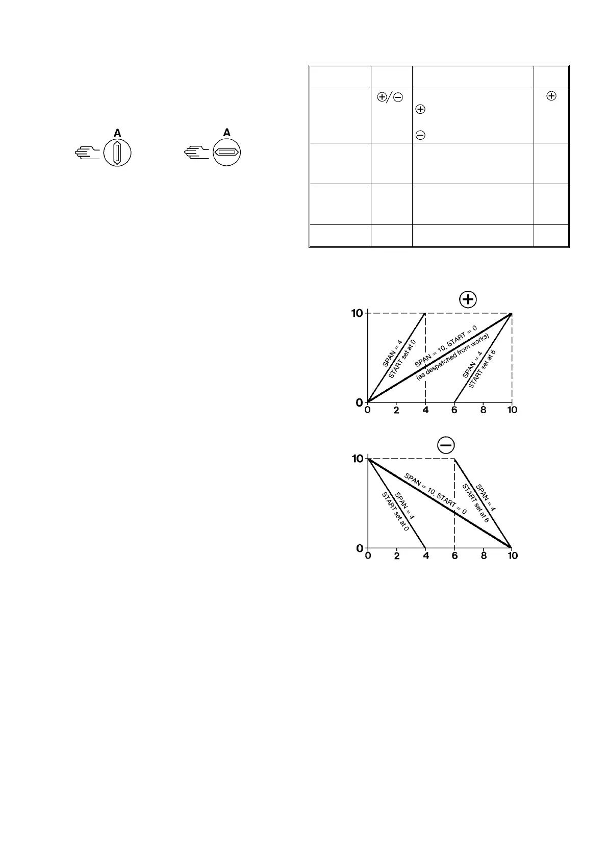
ALE ACTUATOR POSITION FOR TYPICAL SETTINGS OF 'START',
'SPAN' AND 'ACTION'
AUXILIARY SWITCHES
An auxiliary switch kit 831-1-211, comprising two single-pole
changeover switches, is available as a separate accessory. The two
electrically-separate switches can be independently set, one to
operate at any point between positions 0 and 5 and the other between
positions 5 and 10.
(Not applicable to ALX 1251 or ALE 1352, which have one fixed
auxiliary switch built in).
Auto
position
Manual
position
ADJUSTMENT MARKED FUNCTION Factory
set at:
Slide Switch Selects Direct or Reverse Action
signifies increase of actuator
position with increasing input
dc Volt signal.
signifies the reverse of this.
Potentiometer START
(0-10V)
Sets the command signal voltage
at which the actuator
commences to move from zero
position.
0V
Potentiometer SPAN
(4-10V)
Sets the change in command
signal Voltage which will cause
actuator to move through
complete stroke to positing 10.
10V
Potentiometer STROKE Matches operation of actuator to
desired valve stroke.
16mm
Fig.1
Slide switch at
Actuator
Position
Actuator
Position
Slide switch at
Signal Volts
Signal Volts
 Loading...