DS 3.401 8 - 10 11/99
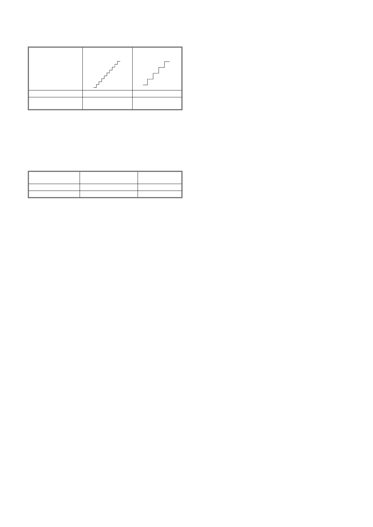
15. Set the required hysterisis for the actuator using jumper 'G'. Low
hysteresis (200 steps) is used for tight control applications using
microprocessor based controllers and standard hysteresis (25
steps) is used for analogue controllers and standard applications.
See the table below for details:-
16. Fit, set and check auxiliary switches, if used, as described for ALM
and ALX (section 9).
17. Replace terminal cover.
ALE WIRING PRECAUTIONS
WARNING -
IF AUXILIARY SWITCHES ARE FITTED AND USED AT MAINS
POTENTIAL, OBSERVE LOCAL WIRING REGULATIONS,
EARTHING REQUIREMENTS AND ALL USUAL SAFETY
PRECAUTIONS.
* When wiring to BAS outstations refer to the appropriate outstation
data sheet for the wiring precautions.
For longer lengths of 24 Volt supply wiring, increase cable size and
observe maximum resistance, also run separate return from terminal 7,
as Fig.12.
Terminals 7 and 10 are both at ground potential, provided for
convenience of wiring.
Where screening is required, use either screened cable, MICC or
cables run in a separate conduit.
Jumper 'G' set to
A-B 200Steps
Jumper 'G' set to
B-C 25Steps
MMC, KMC, IAC, BAS Yes Yes
DRTE, DDTE, DWTE,
CZT
No Yes
Wiring from actuator
to controller*:
Max. length of 1.5mm²
cable unscreened
Max. resistance
per conductor
24V/240V~ supply 100m 5Ω
0-10Vdc signal 100m 50Ω
10Vdc
0Vdc
10Vdc
0Vdc
 Loading...