WARNING:
• To reduce the risk of personal injury or property damage from re,
electric shock, falling parts, cuts/abrasions, and other hazards read
all warnings and instructions included with and on the xture and all
xture labels.
• Commercial installation, service and maintenance of luminaries should
be performed by a qualied licensed electrician. For The installation:
If you are unsure about the installation or maintenance of the
luminaries, consult a qualied licensed electrician and check your
local electrical code.
• Turn off electrical power at fuse or circuit breaker before wiring xture
to the power supply.
• Turn off the power when you perform any maintenance.
• All connections should be capped with UL approved wire connectors.
• Minimum size 18 AWG or 14 AWG for continuous runs.
• Risk of Burn. Disconnect power and allow xture to cool
before handling.
• Verify that supply voltage is correct by comparing it with the
luminaire label information.
• Do not install in a hazardous atmosphere, except where the ambient
temperature does not exceed the rated operating temperature of
the xture.
• Keep tightly closed when in operation.
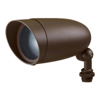
LED LANDSCAPE FLOOD
Models: 62-1200, 62-1201, 62-1202, 62-1203,62-1204,
62-1205, 62-1206, 62-1207, 62-1208
Satco Products, Inc.
Brent wood, N Y 11717
ELECTRICAL REQUIREMENTS:
• The LED driver must be supplied with 120V, 50/60 Hz
and connected to an individual, properly grounded branch circuit
protected by a 20 ampere circuit breaker. Use min. 75°C supply.
GROUNDING INSTRUCTIONS:
• The grounding and bonding of the overall system shall be
done in accordance with NEC Article 600 and local codes.
TOOLS REQUIRED:
• Crescent Wrench
• Wire Strippers
• Wire Cutters
INSTALLATION:
1. Before starting ensure that the power is disconnected.
2. Unpack xture and ensure that there are no damaged parts.
3. Attach xture to outdoor box cover, routing the xture wires
into the junction box. Connect xture cables as seen in
wiring diagram. Black to Black, White to White, and Green
to Green.
Aim xture by loosening bolt on the arm, and repositioning
to the desired angle. Tighten the bolt.
4. Wire end of cord to power supply as seen in wiring diagram.
Wiring Diagram
INSTALLATION AND SAFETY INSTRUCTIONS
IMPORTANT: Read before installing xuture. Retain for future reference.
© Copyright 2020 Satco Products, Inc. 2/20
PRODUCT SPECIFICATIONS:
Model # Volts Watts Lumens Kelvin Lt. Gray Dark Gray Bronze
62-1200, 62-1201, 62-1202
120V
6W 640
3000K
62-1201 62-1202 62-1200
62-1203, 62-1204, 62-1205 9W 900 62-1203 62-1204 62-1205
62-1206, 62-1207, 62-1208 12W 1240 62-1208 62-1207 62-1206
4"
62-1203
62-1204
62-1205
PAR 20 Size
5 1/2"
3 1/4"
62-1200
62-1201
62-1202
PAR 16 Size
(12.204mm)
4 59/64"
62-1206
62-1207
62-1208
PAR 30 Size