2 SATEL SP-500
1
2
3
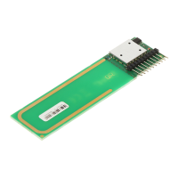
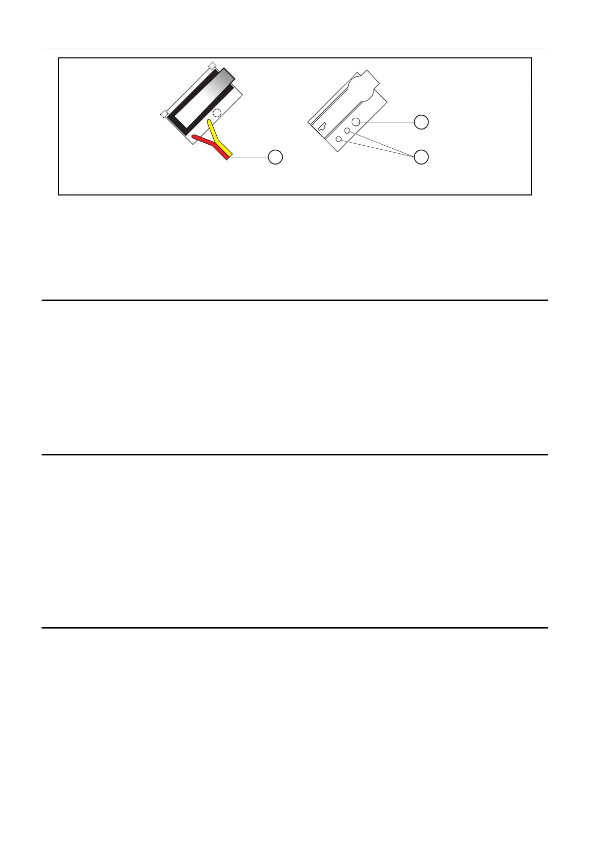
Fig. 2. Tamper element and its equivalent – reed relay switch.
Explanations for Fig. 2:
1 – cables for connecting tamper circuit element with plate
2 – fixing screw opening for reed relay switch
3 – soldering points of reed relay switch
1. Outfit options
Additional protection elements (sold separately) can be installed in the siren. They include:
• inner cover of galvanized sheet, OM-SP500;
• hermetic reed relay tamper switch, SD/SP-SAB.
Where the reed relay switch is used, it is necessary to remove the mechanical switch
installed by the manufacturer on the tamper element, and replace it with the new switch. This
operation requires resoldering of the two cables which connect it with the electronics of the
siren (see Fig. 2).
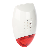
2. Installation
The SP-500 siren is to be installed on a flat surface, in a possibly inaccessible place, so as to
minimize the risk of tampering. The siren should be screwed to its base by means of screws
and expansion bolts (the screws and expansion bolts are delivered with the siren).
Note: Make sure to leave a distance of about 0.5 cm between the upper edge of the siren
base and the ceiling or another element which limits the mounting position from
above. The lack of such clearance can make the mounting of housing difficult.
After the siren has been installed, it is recommended that the fixing screw holes and the
cable entry opening be sealed with silicone compound.
3. Description of siren functioning
The SP-500 siren can work together with any source of alarm signal which, in the alarm
condition, provides 12 V direct voltage on the signaling output (outputs). The audible
signaling of the SP-500 will be activated after connecting the 12 V power supply to the
"+ SA -" terminals, while the visual signaling will switch on when the 12 V power is supplied to
the "+ SO -" terminals.
The "TMP" terminals are designed for connecting the siren to the tamper circuit of the alarm
system.
You can choose one of the three types of acoustic signaling.
 Loading...