SP-500 SATEL 3
JP1
JP2
JP3
JP4
JP5
JP1
JP2
JP3
JP4
JP5
MEL1=JP1+JP4
MEL3=JP3+JP5
MEL2=JP2+JP5
zworka założona
zworka zdjęta
JP1
JP2
JP3
JP4
JP5
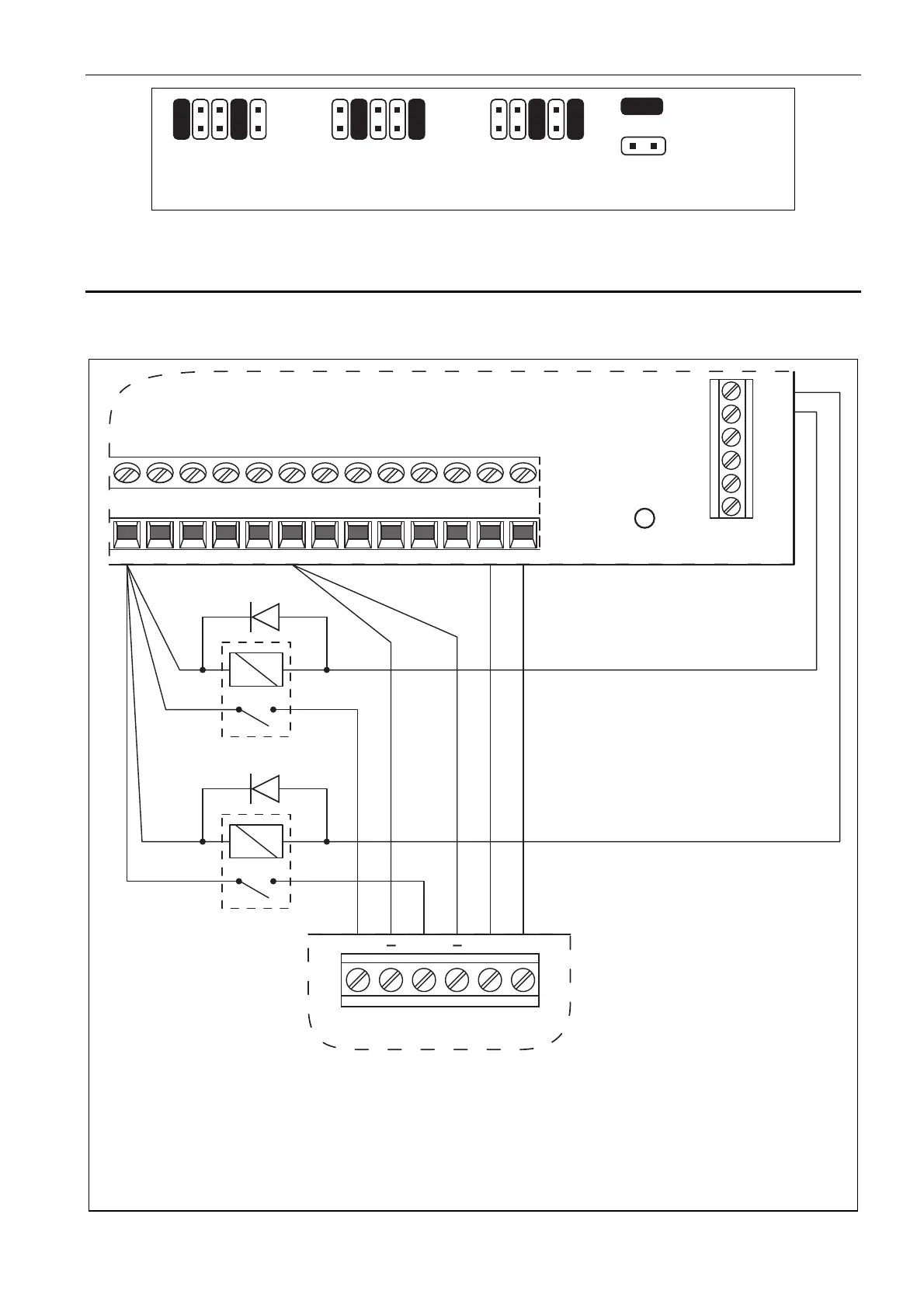
Fig.3. Placing jumpers in different ways across pins to obtain the required audible signal.
4. Hooking Up
It is possible to control two types of signaling from one control panel output when the
terminals are connected in parallel: +SA with +SO and -SA with -SO.
SP-500
TMPTMP
SA
+
SO
+
OUT3
OUT4
OUT5
OUT6
OUT7
OUT8
INTEGRA 32
AUX
Z1
COMCOM
CK
COM
Z2
CKM +EX DT+KPD DTM
OUT2
P1
P2
Fig. 4. Method of connecting the SP-500 siren to low-current outputs of INTEGRA 32
control panel. Output OUT2 has been programmed as supply one. Output OUT3 controls
the relay P1 which triggers acoustic signaling, and output OUT4 controls the relay P2
which triggers optical signaling (low-current outputs with normal polarization are activated
by shorting the terminal directly to ground 0 V). Zone Z2 should be programmed
as 24 h tamper.
– pins shorted
– pins open