Do you have a question about the Satloc IntelliFlow 2 and is the answer not in the manual?
Guidance on interpreting safety alerts and the importance of reading the manual before installation.
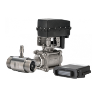
Lists the various flow meter components included in IntelliFlow 2 kits, with part numbers and descriptions.
Details the valve and motor assembly parts for the IntelliFlow 2 system, including part numbers.
Instructions for mounting the controller in an available aircraft space and securing it with fasteners.
Steps for mounting the IF2 controller on an adapter plate when replacing a legacy system.
Shows the recommended setup for the IntelliFlow 2's flow meter and valve/motor assembly.
The Satloc IntelliFlow 2 (IF2) is a precision application control system designed for aerial agricultural, forestry, and demanding eradication suppression spray programs. It integrates with existing GPS systems, specifically the Satloc G4 or Bantam, to automatically control aerial spray rates, ensuring precise and efficient application of liquids.
The core function of the IntelliFlow 2 is to regulate and maintain selected spray rates, whether for a constant flow application or a variable rate based on prescription maps (PMAPs). When installed, the IF2 system works in conjunction with the aircraft's GPS to automatically adjust spray rates. Pilots can enter desired rates through the GPS interface, or PMAPs can be created using Satloc MapStar desktop software. The system then ensures that the actual spray rate matches the selected or prescribed rate. This capability allows for fine-tuning applications through a "rate bump" feature, enabling more precise control during operation. The IF2 system is versatile, supporting flow control options in various sizes: 0.5”, 1”, 1.5”, 2”, and 3” versions, catering to different application needs. It also offers the flexibility to switch between liquid and dry settings with ease, making it adaptable for various types of applications. For dry applications, it can control Transland Hydraulic 5", 7.5", or 10" gate systems directly from the Satloc G4 interface. An optional transducer allows for the display of pressure on the screen and lightbar, providing real-time feedback to the pilot.
The IntelliFlow 2 system is designed to enhance precision in aerial applications, leading to several benefits for applicators and growers. By ensuring precise spray patterns and constant rate flow control, the system helps reduce fuel consumption, flying time, and overall application costs. This precision also contributes to meeting and surpassing the needs of growers, potentially increasing profit per acre. The system's ability to automatically control spray rates based on GPS data or PMAPs minimizes pilot fatigue, as it reduces the manual workload associated with maintaining consistent application. The IF2 control system includes a controller, associated cabling, and necessary unlocks. For liquid kits, it specifically comprises a valve with a motor and a meter equipped with a magnetic sensor, all working in concert to achieve accurate flow control. The installation process involves mounting the controller in an available space within the aircraft, such as the baggage compartment, ensuring sufficient clearance for connections and access for maintenance. If replacing a legacy IntelliFlow system, an adapter plate can be used to mount the IF2 controller, utilizing existing fasteners. The cabling connections are straightforward, linking the IF2 controller to the GPS unit, power source, valve/motor assembly, flow meter, and boom pressure switch. Pilots are advised to store excess cable lengths with a minimum six-inch bend radius and avoid coiling cables to prevent noise. High-temperature exposure, such as near the exhaust, should also be avoided when routing cables. All connections should be hand-tightened, without the use of tools, to prevent overtightening. The flow meter and valve/motor assembly are typically installed in the aircraft's existing boom supply tube. The recommended configuration places the flow meter before the valve/motor assembly to minimize turbulence, with specific minimum hose lengths between components to ensure optimal performance. The length between the bypass valve and the flow meter is particularly critical, ideally being as long and straight as possible, exceeding the recommended minimums when feasible.
To ensure trouble-free operation and longevity of the IntelliFlow 2 system, specific maintenance recommendations are provided. It is crucial to avoid using the IF2 system in extreme environmental conditions; an operating temperature range of 40-140°F is recommended. A key maintenance practice is the thorough and methodical washing of the hopper/boom system after each spray session. This prevents gumming up of the flow meter unit, which can impair its accuracy and functionality. The design of the system, with its robust components, aims to minimize the need for frequent repairs, but regular cleaning is essential for preventative maintenance. When installing, it is important to plan the cable routing carefully, considering cable lengths, clearance space, power source, aircraft structure, and visibility. This thoughtful installation contributes to easier future maintenance and troubleshooting. Support fittings for the flow meter and valve/motor assembly should not be connected directly to these components but rather use stainless wrap-around straps and supports, which facilitates inspection and replacement if necessary. In case of any questions or issues, Satloc Customer Service or local dealers are available for support, emphasizing the importance of proper installation and adherence to safety guidelines outlined in the manual. Reading and understanding the manual thoroughly before installation, operation, or maintenance is paramount to prevent irreversible damage to the system.
| Category | Control Systems |
|---|---|
| Product Name | IntelliFlow 2 |
| Manufacturer | Satloc |
| Flow Control Accuracy | ±2% |
| Mounting | Vehicle cab |
| Features | section control |
| Type | Automatic Flow Control System |
| Compatibility | Various spray booms and application equipment |