3
Names of components
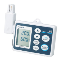
● Main unit
①
LCD: Displays the temperature reading and
state of the unit.
② LED lamp :
Flashes while the alarm is sounding.
③ Power/Backlight key :
Turns the power on or off. Also used to turn
on the backlight.
④ REL/SET/ESC key :
Activates the REL function. Also used to
switch between the measuring mode and
setting mode.
⑤ MAX/MIN/▲ key : Switches between MAX and MIN. Advances the items or values in the setting
mode. Also used to turn on or off the display of current logging.
⑥ HOLD/T1 – T2/▼ key : Freezes (holds) the measured value. Also used to switch between T1 and
T2. Resumes the items or values in the setting mode.
⑦ REC/ENTER key : Starts logging. Confirms the values in the setting mode.
⑧ MEMO : Activates the MEMO function.
⑨ Lid of SD card slot : The SD card is inserted under this lid.
⑩ AC adapter terminal : Terminal to which the AC adapter is connected
⑪ Thermocouple terminal : Terminal to which the thermocouple sensor is connected. From left to right,
channels 1, 2, 3, and 4.
⑫ Lid of battery compartment : The batteries are installed under this lid.
⑬ Hook hole for wall mounting : Used to hang the unit on the wall
⑭ Reset button : Resets the error state.
⑮ Tripod mounting hole : Threaded hole for mounting on a tripod
①
② ③ ④ ⑤
⑥ ⑦
⑧
⑨
⑩
⑪
⑫⑬
⑭
⑮
⑨
 Loading...