å
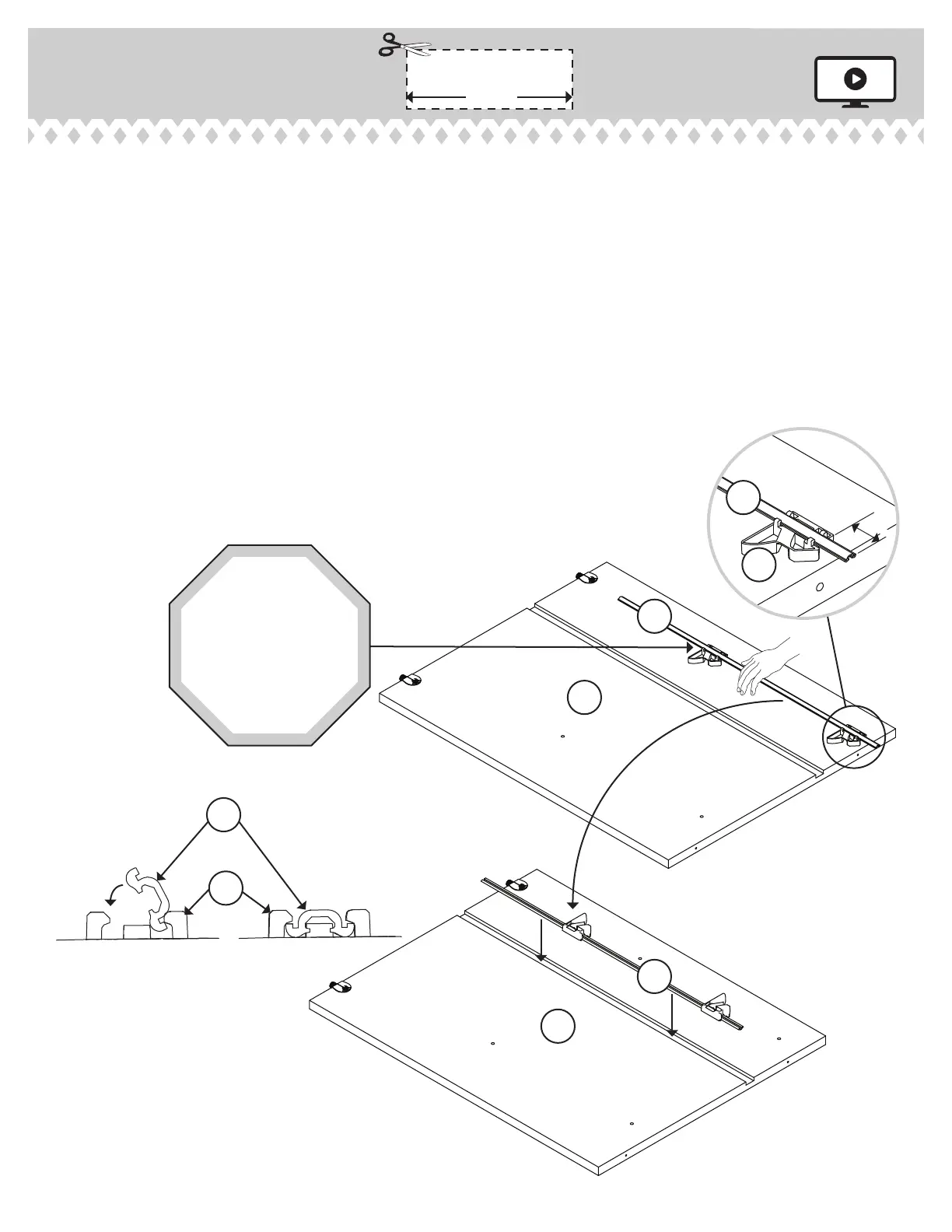
Diaram 1. Measure 1-1/2" from one end of the INTERLOCK TRACK (22G). Position the
INTERLOCK TRACK as shown.
å
SAFETY STOP / TRACK ATTACHMENT:
å
Diaram 2. Tilt the fi rst ede of the INTERLOCK TRACK (22G) into the SAFETY STOP (29G).
å
Diaram 3. Rotate the INTERLOCK TRACK and apply force to snap the second ede into the
SAFETY STOP.
å
Diaram 4. Repeat the SAFETY STOP/ TRACK ATTACHMENT for the next SAFETY STOPS
while holdin the previously completed SAFETY STOP in its location hole. Visually check
that all INTERLOCK TRACK edes have been snapped into the SAFETY STOPS as shown in
diaram 3.
å
Diaram 5. Remove the INTERLOCK TRACK assembly from Diaram 4 and fl ip it over
before insertin the INTERLOCK TRACK (22G) with SAFETY STOPS (29G) into the roove
in the INSIDE RIGHT END (C3).
Step 4
412015www.sauder.com/services
Pae 9
C3
C3
Cut out this rectanle
to use as a "spacer"
1-1/2"
4.
5.
1.
1-1/2"
29G
2. 3.
29G
22G
22G
22G
22G
STOP
Be sure the
interlock track
snaps into each
safety stop.
F
L
I
P
O
V
E
R







 To Next Page