55.011
Sauter Components
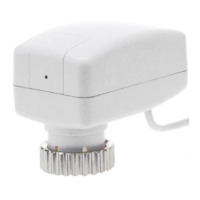
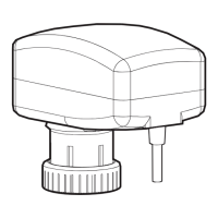
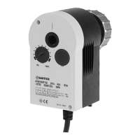
AXM 117S: Motorised drive (with positioner) for unit valves
How energy efficiency is improved
Automatic valve adjustment and intelligent cut-out enable maximum energy efficiency.
Areas of application
Actuation of through and three-way unit valves in the VUL, BUL, VXL and BXL series. For controllers
with continuous output in combination with intelligent unitary control systems.
Features
• Pushing force 120 N
• Fits onto valve with M30 × 1.5 thread
• Stepping motor with control and electronic cut-off
• Version with control action A or B or adjustable
• Maintenance-free gearbox
• Suitable for retrofitting existing installations using an appropriate adaptor
• Operating status control using integrated LED display
Technical description
• Two-part plastic housing, light grey (RAL7035)
• Nickel-plated brass nut
• Connecting cable, light grey 1.50 m long, 3 × 0.25 mm²
• Running time for 4 mm stroke: 60 s
• Installation position: vertical to horizontal, but not upside down
Operation
During commissioning (with valve fitted), the actuator moves to the two end positions and memorises
the number of steps taken to do so. The 0...10 V control signal is then linearly assigned to this effec-
tive stroke. The motor activates the valve and switches off as soon as the stroke position concurs with
the controller signal. In the end positions or in the event of an overload, the motor is switched off with-
in 2 minutes. If the control voltage has not changed for 2 hours (in the range 0...0,5 V), the motor –
after approx. 2 hours – runs briefly to the end positions and, if necessary, corrects its position
memory. A complete cycle is performed every 24 hours on the AXM117SF202 and F302 in order to
prevent the plug from jamming. The LED lights up when power is applied to the drive, and flashes
when the motor is running.
100 %
0 V Output signal y 10 V
B07650
0 %
Direction
of operation 2
Direction
of operation 1
1)
2)
2)
3)
2)
Power consumption on
starting
0...10 V; 5,2...10 V; 0...4,8 V
Max. operating temperature
Adaptor for fitting to Oventrop valves (M30 × 1)
Adaptor Danfoss RA2000, 22 mm
Adaptor for fitting to Beulco or Tobler underfloor-heating distribution stations (M30 × 1)
Adaptor Danfoss RAVL, 26 mm
Adaptor Danfoss RAV, 34 mm
Adaptor for fitting to Herz valves, type Herz-TS’90 (M28 × 1,5)
Adaptor for fitting to Tour & Andersson valves, type TA/RVT (M28 × 1,5)
Direction of operation 1: rising 0…10V = drive retracts (VXL, VUL, BUL opens, BXL control passage closes).
Direction of operation 2: rising 0…10V = drive extends (VXL, VUL, BUL closes, BXL control passage opens).
Pushing force: min. 100 N, max. 150 N
The direction of operation and the setting of the control voltage can be set using jumpers